Welcome to the SR20 Community Forum - The Dash.
Register
SR20 forum logo

Thread: What to do next?

+ Reply To Thread
Posts: 31-40 of 48
2012-10-25 21:00:49
#31
What happened to the K20 Intake idea?
2012-10-25 21:09:45
#32
Still in my head, i just dont have any extra time...
2012-10-25 21:15:18
#33
Or do something similar to an rb25 intake manifold but have two throttle bodies feeding directly in

I dont think what I posted would be hard or that expensive to make either.

I think the hardest part would be figuring out the throttle actuation of both throttles using one cable which really wouldnt be that hard. I have several ideas that could easily accomplish that.
Last edited by ashtonsser on 2012-10-25 at 21-16-09.
2012-10-25 22:01:33
#34
Originally Posted by Nicoxis
Something like this


Awesome photoshop skills LOL


I would love for somebody to try it but I think the amount of work and modifications it would require, would far outweight the potential benefits.

You would have to cut the plenums on the end, to fit and you would have to modify the bottom of the plenum to allow the runners to fit/line up properly. This would be a lot of work. The other option would be to cut out the bottom part pf the plenum and make a custom bottom plate to allow the stock runners to mount up. At this point you are re-enginerring the VE plenum and it is no longer cost-effective. It would be cheaper to just make a custom plenum with off-the-shelf pieces.

The other problem with this set-up would be the requirement of two TB's, two TPS's and two MAF's. You would have to account for the extra wiring for these items. Also, I don't believe you could just splice into the existing harness as it would change the voltage outputs for each signal, with double the load. Now, you may be able to account for this with a stand-alone ECU and voltage adjustments, but I just don't know how this would work.

I would assume that a setup like this would require a stand-alone ECU and possily different sensors, i.e. getting rid of the MAF altogether and tuning with speed density? I don't know enough about how this would work (speed density).

Maybe a "tuner" could chime in on this two TB/TPS/MAF vs no MAF and speed density set-up and let us know what they think? Am I on ppoint with my theories?


I think the best bet might be a RAM air type manifold, seperated into two seperate chamber/inlets wiith dual TB's and no MAF. Very similar to the TB Motorworx setup that Nismo94tuner posted. This would keep the flow equal for both sets of cylinders, make the manifold design somewhat simple and allow for more flow to each set of cylinders (with the dual TB). The TB linkage could be shared/have shared TPS as well. The inside of the plenum would have trumpets built into the base of the plenum.

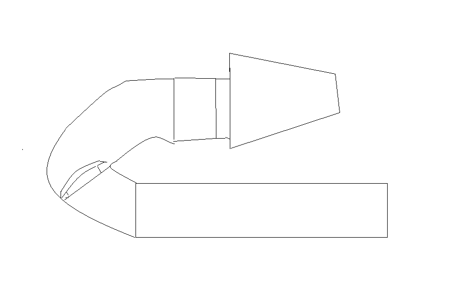
Something like this....

Side view of cylinder head with plenum/trumpets and air filter. DOn't mind the dimensions as I used paintshop. You get the idea anyway


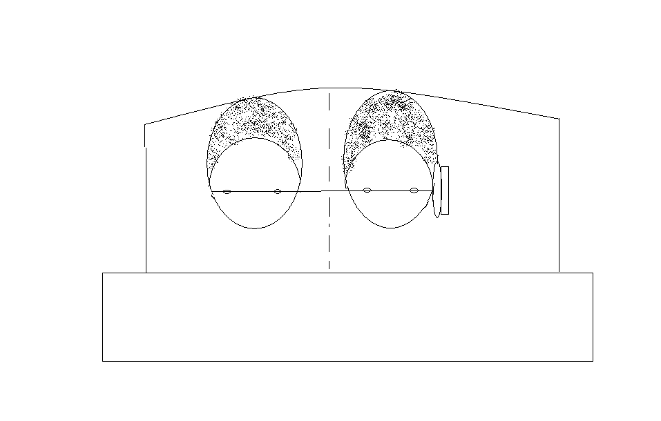
Front view of engine with split/dual runner setup with dual TB's and shared TB linkage/TPS setup. The dotted line shows the divided chamber for each set of cylinders.


Hopefully my simple drawings will be easy to understand...This would definitely be custom but would be cheaper than ITB's. You could make the bottom part of the plenum/runners the length you wanted based on your setup. The top portion would just be tubes of any length you wanted, Also, the throttle plates could be moved anywhere in the tube to account for desired throttle plate to valve head length. A set-up like this could have lots of different tuning possibilities based upon lengths and dimensions of tubing, runners, TB placement etc.

Just a thought.
Last edited by B15NEOVVL on 2012-10-25 at 22-05-59.
2012-10-25 22:26:39
#35
I think one does not always think about all the implications of a wild idea, but you nailed it on the key issues. It would make a phenomenal "educational" project though, seems like a lot of fun.

The alternative you mention looks much more plausible, I like how is shares the TB mechanisms.
How would one calculate the different lengths on that setup? I mean runners, plenum size, upper tubes, TB size and so on..
2012-10-25 22:48:01
#36
Originally Posted by Nicoxis
I think one does not always think about all the implications of a wild idea, but you nailed it on the key issues. It would make a phenomenal "educational" project though, seems like a lot of fun.

The alternative you mention looks much more plausible, I like how is shares the TB mechanisms.
How would one calculate the different lengths on that setup? I mean runners, plenum size, upper tubes, TB size and so on..


I would calculate all of the necessary values with relative ease......by paging somebody who knew those answers.

Honestly, there are so many variables and not many people know them. It would really take alot of tuning and messing around to find the best value for each variable, such as size, length, angle of runners etc. A tuner with hands on experience would know best. Everything else is just theory and conjecture.

As far as ITB's go, there definitely are specific values which will change power on-set and peak. Various values such as trumpet length/angle, length from valve head to throttle plate/end of horn, how far the throttle plate is from the end of the runner, even which way the throttle plate opens up (pivot vs slide is also a consideration). There are so many variables that control where you make your power and how much you make.

In the plenum setup I drew, I would think that some of these principles would apply. Simply by the nature of the design. I definitely don't have the answers but I like to research, so who knows...


Edit: Here is a link to a cool article I found a while back...circa 2008

ITB: The Way It Should Be
Last edited by B15NEOVVL on 2012-10-25 at 22-55-08.
2012-10-25 23:42:21
#37
Originally Posted by Nicoxis
Originally Posted by B15NEOVVL
Originally Posted by Nicoxis
What about using two SR20VE intake plenums with their stock TB and cutting the plenums in half to fit them?

Would be a cheap and fun experiment IMO


That might be a fun experiment but the plenum chambers would still have to be seperated by a wall, for each set of cylinders (1/2 and 3/4). Otherwise, the air flow from each section would "smash" into eachother. They could not be combined to form 1 complete chamber.

Maybe this is what you meant anyway?


Something like this


Awesome photoshop skills LOL


I know it's hypothetical, but that design is not a good idea. The pairing of 1,2 and 3,4 would result in the cylinders stealing air from each other.

Remember, we have a 180*/flat crank with the firing order of 1-3-4-2. When cylinder 3 is on the intake stroke and reaches bdc, cylinder 4 will start to open and rob cylinder 3. Same thing will happen to cylinder 2 when cylinder 1 starts to open. The induction phase is 300* plus for a N1 cam so that mean there's a 120* of induction overlap. That why big plenum work. Better to pair 1,4 and 2,3. Now it's 360 separation in the induction cycle.
2012-10-25 23:52:51
#38
Reverse the head and put the intake up front.
2012-10-26 06:13:37
#39
^I wish.
2012-10-26 08:18:35
#40
Originally Posted by nismo94tuner
Lol. Placement of a larger throttle body sucks because you need a radical bend to clear the MC. Definitely would not boost this motor. I would build another stock sleeved motor to handle the boost


Get a rhd car
+ Reply To Thread
  • [Type to search users.]
  • Quick Reply
    Thread Information
    There are currently ? users browsing this thread. (? members & ? guests)
    StubUserName

    Back to top