Welcome to the SR20 Community Forum - The Dash.
Register
SR20 forum logo

Thread: Do P12 20v coil plugs have built in ignition modules?

+ Reply To Thread
Posts: 41-50 of 65
2012-02-20 16:38:58
#41
Originally Posted by BenFenner
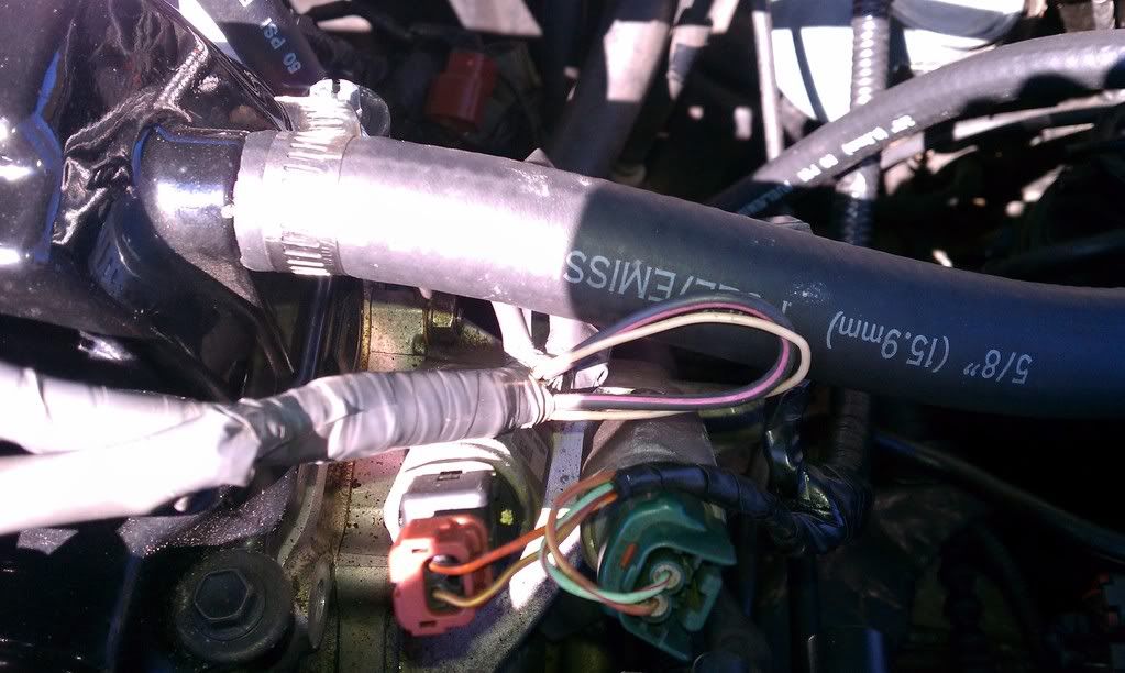
Okay, Ashton says you check ignition timing on the ground wire. The OEM diagram says the loop is on the power wire. I've not had much luck with with the power wire in the past. I've not had much luck with the signal wire either. I never tried the ground wire because in the past that was in the cabin (only had 2-wire COP).

Soooo, I think I'm going to leave all three wires loose for now and then do some testing to find out which one (if any) of the wires gives comparable information on a typical timing light. I'll use the timing information gathered after the coil for comparison and put this guess-work out to pasture once and for all. (I assume you went through all this on the F20C AE86 Ashton?)


Yes, when we did the f20c we used the timing light on the ground wire. I think it worked on both though. I guess it depends on how sensitive the timing light is too.

On my cop setup i could use either and either would give me the same result but that was a 540v positive so yeah.

On a smartcoil setup where the ignitors are built in I would probably try the positive wire but again the same affect should happen. All its looking for is a magnetic field from the pulses.


All i know is on the f20c the first two timing lights we tried wouldnt work, then we got a nicer one from a buddy and it worked just fine.
2012-02-20 16:49:16
#42
You know Ashton, your examples have all used CDI, correct? CDI boxes "steal" the dwell time and then fire almost instantaneously (often times semi-independently of the actual ECU timing), which would explain why you get accurate timing info from those setups.

I think we're figuring this out.
2012-02-20 17:21:55
#43
The s2k motor used the stock ignition. lol.

Mine was on a cdi box. But, it was also setup to where the ecu, which it does, controlled dwell time, not controlled by the cdi box itself. You can set it to where it does its own dwell and firing and then just looks for the first signal of the ecu or it continues to allow the ecu to control dwell time.

Which is the way I had it set up. Plus got accurate readings as well. I mean as soon as the timing light sees that pulse the plug pretty much instantly fires. I mean ideal would be to read the spark actually going down from the coil but thats not going to happen. But its so instant anyways i doubt its any noticable amount off from reading timing at the pulse of the positive or negative wire of the coil.

If you cant get a signal with your timing light, like MrSentaSpecV said, try one or the other or maybe both the positive and negative together and see if it can pick up a signal that way. Either that your timing light just isnt sensitive enough to do a COP signal read.
2012-02-20 17:24:37
#44
ask and you shalt receive


as you can see u need 2 wires for the 20v coils. you could always use a spark plug wire modded to go in between the plug and cop. they make lights to check COP that work that way. i am sure you could make it work in a pinch
2012-02-20 17:26:40
#45
So its got the positive and trigger signal looped to read timing, guess that would work just fine being the pulse will go off in both wires at the same time.
2012-02-20 17:31:55
#46
That is so weird for so many reasons. That's stock? Geez.
Also, that thicker wire is the power wire, but it splits off after that and connects to all four coils I believe. So it is going to experience pulses for all four coils. Sooooo weird. O_o

Unless that thick power wire doesn't feed all four coils from there. I just took my stock 20V COP harness apart and the grounds are shared, and the power is all shared too.

It looks like experimentation is going to have to happen, but at least I have tons of things to try now.
2012-02-20 17:33:51
#47
yea its 100% stock Nissan s15 harness.
2012-02-20 17:43:03
#48
More than likely its the wires going to the number 1 after the split, being looped back around. A lot of cars do this. I think the s2k harness had one of those loops as well but I didnt see it till later. Either way using the coil ground worked just fine once i got a decent timing light.
2012-02-20 17:52:47
#49
Originally Posted by ashtonsser
More than likely its the wires going to the number 1 after the split, being looped back around.
I'd considered this. You're probably right. After re-doing my harness this weekend I've seen it all now. OEM harnesses are nucking futs. It's like it evolved into what it is instead of being designed by a engineer. Tons of crazy shit you'd never do in a million years. Tons of extra, tons of loop-backs, tons of wires when one would do.

The entire ECU is grounded by two 18-ga wires to the intake manifold. You heard me right. Just two. Not four. Those two extra 18-ga wires coming from the ECU ground terminals? They loop back to each-other. They are like a ground balancer. So for all the thick gauge power wires running around the harness, they all ground through those two wires. Double-u tee eff mate? I'm going to two 10-ga grounds.
Last edited by BenFenner on 2013-03-07 at 17-13-10.
2012-02-20 18:06:29
#50
Oh, I found a section of the FSM wiring diagram that is wrong. I've penned it in on my copy. It regards the knock-sensor shielding pathway, so doesn't really belong in this thread. ^_^
If you made your own harness sticking strictly to the FSM diagram, you'd end up with a large section of the knock sensor signal wire unshielded (the injector/knock sensor sub-harness side).
Last edited by BenFenner on 2012-04-18 at 23-05-04.
+ Reply To Thread
  • [Type to search users.]
  • Quick Reply
    Thread Information
    There are currently ? users browsing this thread. (? members & ? guests)
    StubUserName

    Back to top