Welcome to the SR20 Community Forum - The Dash.
Register
SR20 forum logo

Thread: Thoughts on a full race motor setup

+ Reply To Thread
Posts: 221-230 of 333
2008-12-20 16:40:32
#221
Are the second set of injectors for fuel?
Is there any way you can get them out of the way of air flow? Maybe opposite the main injector rail?
2008-12-20 18:16:09
#222
Originally Posted by mrslappy
I have built 3 intake manifolds for the DE motors and I had one built with the throttle body positioned up towards the top of the firewall and the hood crease. I believe this added too much volume to the plenum though as by changing the shape of the plenum and removing about 30% of the volume and putting the throttle body at a less than 90 deg angle ( similar to the Honda 06+ SI intake manifold and keeping the plenum with the flow travel of the throttle body, (keeping everything else the same), The second one made more power everywhere. It also had a better intake note to it. The design of the plenum also has a great deal to do with whether or not the intake runner entrance is flush radius with the plenum floor or if the velocity stacks are raised up off the floor.

That AIR intake manifold was designed by an engineer years ago and it makes more power than any other setup ( for a B series) that I have seen ( even 50mm ITB setup).

The fluid flow of the intake is also greatly effected by the intake pulses from the intake valves opening and closing.


that links nicely to this old thread:
Let's talk about bearing clearances - SR20 Forum

"...Other tests have shown that the Counterweight center of gravity and actually different weight counterweights (on a 4 cyl crank) yield far better dynamic balance than the "eye" pleasing perfectly symetrical 8 counterweight crank.
These studies were initiated by the NASCAR guys who had perfect correlations of wear patterns on two specific main bearings, regardless of bearing type, oiling, brand etc.
The original Porsche 928 V8 had a simillar problem, traced back to the inlet manifold design..........same problem as on a 4 cyl where #3 and #4 fire sequentially......the low pressure on the inlet of one cylinder (because one right next to it just sucked all the air) alters the in-chamber pressure at TDC on the next adjacent cylinder..........the combusted "gas effect" translated to wierd behavior on the crank journals of the two. They cured it by changing the configuration of the inlet manifold.

SRs like to kill #3 Main right, 3 fires before 4. 4 is starving for air as 3 just sucked the air at the entrance to the port runner. Now 4 fires, 3 is on ex stroke and has the highest rod loading in tension as it is pushing gas through an open system. 4 completes the combustion stroke while 2 has been in compression. 3 and 2 are sharing the same main journal (#3) and has a compressive load on one side (2) and a tensile load on the other (3). The effect is quite possibly detrimental to the #3 Main Bearing.
Only guessing as it's hard to prove on the SR. Been seen and proven elsewhere though."


Something to think about.

Mike
2008-12-20 20:54:13
#223
Originally Posted by BenFenner
Are the second set of injectors for fuel?
Is there any way you can get them out of the way of air flow? Maybe opposite the main injector rail?


ideally you want that second set of injectors to be as far up the intake track as possible.

the ones closest to the head are for start up and lower rpm and the ones further out are for high RPM

Examples
http://www.k20a.org/upload/honda-accord-btcc-injection.mpeg

evolutionm.net - View Single Post - Kinsler EVO intake manifold....rad
2008-12-20 22:01:51
#224
I would like to get the injectors slightly futher back because they are quite close to the trumpet inlet but this is dictated by available space between the head and the strut tower. Once I test fit the motor back into the car i'll be able to get a much more accurate idea of how much room I have to play with.

Do you have anymore info on that K20 motor, I'd like to see a bit more detail on how they have mounted their stand off injectors, As plumbing those is certainly proving interesting
2008-12-20 23:24:04
#225
hmm nice design there! these are utilised the same way on a f22 build(sohc) by bisimoto without the cover, meaning the trumpets are exposed to the open..
on the evo manifold.. i believe that was made for a special motor, i have a couple of pics, it was made by a japanese company for hks which i dont recall the name they made both the drysump system, and intake system..
i have an intake custom done to correct the problems on the stock unit.
2008-12-20 23:29:46
#226
The reason I cut the manifold right behind the injector bosses was to get rid of as much of the reverse taper as possible. I'd be interested to see some pictures of your manifold
2008-12-22 09:19:31
#227
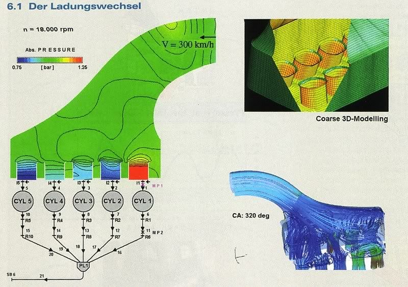
I've got hold of some CFD software (flow and thermodynamics software)
I'll have a play round with it with a few of my manifold designs over the next month or so (as time allows)
But I was thinking once I get a bit more proficient at using it, perhaps I could start a thread and I could start getting some ideas on potential manifold designs that people would like to see tested, I will model them up and run them through the CFD software and hopefully that way we could perhaps see (in theory) what may or may not work.
One thing that I will state now is the trick with CFD software is getting the right answer out of it. It is very much one of those things where you have to input the data correctly, You will always get an answer but if you've inputed the data incorrectly the answer you get will not be at all applicable to what is actually happening. This is why I say I need time to get proficient with it.
I'm also away from work for a few weeks so won't be able to do anything, so it will probably be a month or two before I can start to look at peoples ideas.
2009-01-14 14:48:22
#228
Originally Posted by Andreas
You do realize the TB will be in the fire wall of a FWD SR20 no matter what you do.

Originally Posted by BenFenner
Not no matter what.


Finally, a picture to prove my point.
2009-01-14 14:52:02
#229
You do realize that is not the same manifold designyou posted. Your manifold had the angle facing toward the fire wall.

If you had an idea of what the manifold would look like you would have said so or made a pic of it.

This is not the first time I have seen this manifold design posted here on a FWD car.
2009-01-14 14:52:30
#230
Better picture:

+ Reply To Thread
  • [Type to search users.]
  • Quick Reply
    Thread Information
    There are currently ? users browsing this thread. (? members & ? guests)
    StubUserName

    Back to top