Welcome to the SR20 Community Forum - The Dash.
Register
SR20 forum logo

Thread: Thoughts on a full race motor setup

+ Reply To Thread
Posts: 231-240 of 333
2009-01-14 14:56:07
#231
At the end of the day it is a nice car.


They do not need that hose coming from the PCV valve. They can block it off.
2009-01-14 15:00:14
#232
Originally Posted by Andreas
You do realize that is not the same manifold designyou posted. Your manifold had the angle facing toward the fire wall.
Sure, the TB mounting flange was in a completely different place. Yah, the exact manifold design I posted wouldn't have worked. The manifold I posted was just to show what flow characteristics you'd see if you could get the air entry way pointed at a bit of an angle towards the runners.

I wasn't ever really suggesting that exact design, just something like it.

Originally Posted by Andreas
If you had an idea of what the manifold would look like you would have said so or made a pic of it.
I did have an idea and described it in the previous posts. The idea wasn't as good as what these guys from Jamaica came up with though.
I would have drawn a pic if someone had asked for one. =/

Originally Posted by Andreas
This is not the first time I have seen this manifold design posted here on a FWD car,
Okay. Sorry for the confusion. I wasn't married to the TB flange being exactly where it was in the flow analysis picture I posted (its for a 240Z engine). That's where we had our confusion. I took "no matter what you do" a bit more liberally than you did.
2009-01-14 15:05:49
#233
OK, Now that I got ya on this and you admitted to me that the manifold you posted is basically like this one.

I want you to take a look at the manifold you posted, then take a look at the one you posted before and tell me they will flow the same.

I want you take a close look at the designby the neck and come back with your findings. When doing so thing fluid flow and tell me where the air is going to flow when going around the bend. Then tell me how it will flow on the first one.

You see the first one you posted will flow way better than the one on the Pulsar and the bend in the front of the Pulsar messes up the intake manifold design.
2009-01-14 15:14:20
#234
Originally Posted by Andreas
tell me where the air is going to flow when going around the bend.
The air will favor the outside of the bend.

Originally Posted by Andreas
Then tell me how it will flow on the first one.
In the first one, there's no telling what the pipes do before the TB, but in the test it assumes ideal air density distribution throughout the entire pipe.

I see what you're getting at here and I agree. The bend does mess things up a bit for the recently posted manifold. That's not to say you can't design around that problem, but it would seem they did not.

Also, I don't exactly like their treatment of cylinders 1 and 2. I'd prefer more of a taper in the plenum there. Maybe they did it for sheer volume? Who knows...

Yes, it doesn't live up to the manifold design I posted previously, but the idea is there and I'd still argue it could be done properly, taking advantage of an angled entryway to the plenum.
2009-01-14 15:52:59
#235
The unfortunate part is that you can design the perfect manifold that has perfect fluid flow and resonance and runner length but there are still other things to consider that currently do hinder the performance of these motors at this time.

I have built 2 intake manifolds with the T/B facing towards the firewall on NA setups and they do not perform the best. having the T/B flange angled and facing more towards the drivers front headlamp ( in that general direction) does work better. Low port head, GTiR head, VE head, all of these in built NA trim respond very similar.

One problem with the T/B angled up towards the firewall is that you can not get long enough runner length without actually having to cut the firewall. The other is that when you have that gradual flare going into the plenum if you do not have enough volume of air being consumed by the motor, you will get a low pressure zone in the plenum just behind the throttle body as the air disperses, distributes and flows around the plenum.

Being that I have built several intake manifolds and actually tested theory and design on these motors and not just thought about what should work or what should be better, I can actually give solid facts on what works.

The manifold pictured above on the red car is a RWD aftermarket manifold cut and modified for FWD. Again, those were never designed and intended for N/A application, let alone for a SR20VE N/A motor.

You can build and design all the manifolds on cad and on paper but until you build it to fit the car and actually run it on the dyno to see if it makes power, I would not argue the "correct" placement of the T/B until you have actually done so.

-Ted
2009-01-14 15:57:49
#236
I like the bend for NA


I dont like the bend for turbo.
2009-01-14 16:07:16
#237
mrslappy,
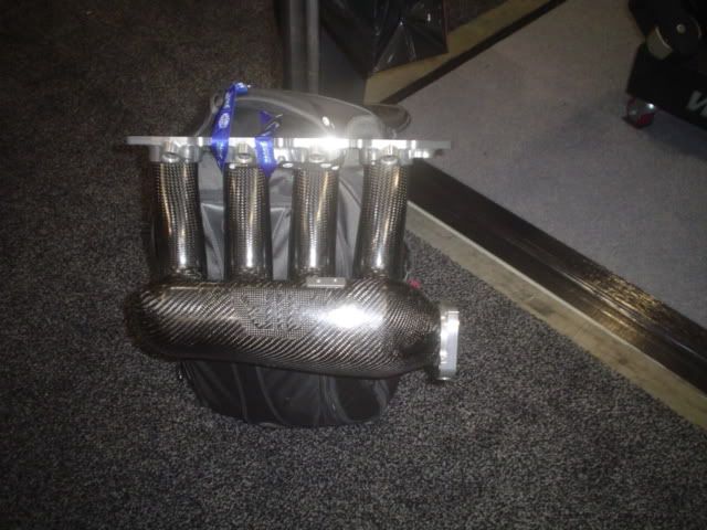
To be fair, we're all talking about turbo manifolds (carbon fiber Honda intake manifold until now) not N/A design. Obviously we're in the wrong thread though...
2009-01-14 16:11:42
#238
Originally Posted by BenFenner
mrslappy,
To be fair, we're all talking about turbo manifolds (carbon fiber Honda intake manifold until now) not N/A design. Obviously we're in the wrong thread though...


That AIR carbon fiber B series manifold was an NA design. I have seen one of the original ones 4 years ago. A friend of mine that Raced USTCC had one sponsored to him for a season. That manifold was made into a cast aluminum piece before being made into a Carbon one. It was also designed, built and tested before it was even put on a turbo motor. The original Carbon fiber ones were too thin and cracked under boost. The Full race intake manifold is modeled after the AIR intake but the Full race one was made from cast for cost reasons and also because it was made for boost from the get go.
2009-01-14 18:33:48
#239
Thanks for the history lesson Snickers. I didn't know anything about it, and was only going on what the poster said (that is was built to handle 35 psi) so I treated it as a turbo intake manifold. :o
2009-01-16 16:39:17
#240
Originally Posted by SERacer
I went to the PRI show over the weekend. I saw a guy walking around with this piece on his tote bag. I chased him down and had to snap this photo. It's for a Honda. Made of carbon and aluminum, beefed up for about 35 psi of boost. Its still in the development stage. May retail for about $1200. The guy was not sure if it will make to market. That's what it's going to take.


That is what the gentleman told me about the manifold. On going development?
+ Reply To Thread
  • [Type to search users.]
  • Quick Reply
    Thread Information
    There are currently ? users browsing this thread. (? members & ? guests)
    StubUserName

    Back to top