Welcome to the SR20 Community Forum - The Dash.
Register
SR20 forum logo

Thread: Thoughts on a full race motor setup

+ Reply To Thread
Posts: 211-220 of 333
2008-12-18 03:18:05
#211
Is Floworks/Floexpress an add on to cosmos or a separate program altogether.?
2008-12-18 03:18:56
#212
FloXpress is part of base solidworks

FloWorks is addon cosmos module
2008-12-18 03:58:35
#213
Originally Posted by Andreas
You do realize the TB will be in the fire wall of a FWD SR20 no matter what you do.
Not no matter what. That plenum design could easily fit on a FWD SR20 car if the runners had a 45 degree bend to them so the TB could face the part where the hood meets the cowl. Should be plenty of room.

Originally Posted by nick
Hey ben what program are you using for your flow analysis?
I didn't make those images. They were taken from a Hybrid Z thread to show general plenum design theory.

Originally Posted by wnwright
You do realize this is nothing like the pictured manifold you are trying to relate it to right? Try again. The plenum pictured should flow very nicely.
I wasn't trying to match it exactly, just showing the general gains from pointing the TB flange at a better angle. I did the best I could to find relevant images. Apparently what I was trying to get across wasn't clear.

Originally Posted by Andreas
Also he need to realize that the problem is not any where as bad on a 4 cylinder as it is on a 6 cylinder.
Again, wasn't trying to ruffle so many feathers...
2008-12-18 04:26:33
#214
I have built 3 intake manifolds for the DE motors and I had one built with the throttle body positioned up towards the top of the firewall and the hood crease. I believe this added too much volume to the plenum though as by changing the shape of the plenum and removing about 30% of the volume and putting the throttle body at a less than 90 deg angle ( similar to the Honda 06+ SI intake manifold and keeping the plenum with the flow travel of the throttle body, (keeping everything else the same), The second one made more power everywhere. It also had a better intake note to it. The design of the plenum also has a great deal to do with whether or not the intake runner entrance is flush radius with the plenum floor or if the velocity stacks are raised up off the floor.

That AIR intake manifold was designed by an engineer years ago and it makes more power than any other setup ( for a B series) that I have seen ( even 50mm ITB setup).

The fluid flow of the intake is also greatly effected by the intake pulses from the intake valves opening and closing.

2008-12-18 13:56:17
#215
that looks alot like a designs that i saw on an f1 intake manifold..... we really need a well designed intake manifold and... well there are good headers... keys
2008-12-19 18:01:07
#216
Originally Posted by mrslappy
Ashton, Glad to see you were using stock head bolts. The ARP's i have seen far too many problems with them. If you used new stock headbolts, then there are a few steps in between what the service manual says. You must make sure you pre torque the headgasket atleast 2 times with a NON FACTORY type. This means a Mazworx, P12, and any other non factory gasket. I say P12 because these motors do not come made with a multi layer gasket from the factory. you should pretorque the head gasket atleast 2 times. 30lb ft then 60lb ft. then loosen then all. then do that again. then go to 30lb ft and then angle TQ with a DIGITAL wrench or digital angle gauge. none of that "1/4 turn give or take" crap. I do NEW stock head bolts to 110 deg then LOOSEN all the way again and go back to 100-102 deg. if they are used bolts I will go right to 100-102. Dont forget these motors are 2 angle TQ settings not 1.

You should be able to re-use that gasket is the sleeves slipped but it is possible that it is damaged beyond use.

Donttazemebro, nice stuff. I have had a bad incident with a cometic head gasket as well. didnt last a week. I machine stock p12 headgaskets out up to 92mm but with the mazworx gasket out, i may not do that as much.

Joels build looks good. not too much info about it though. The header is pair'd wrong though.

1/4, 2/3 pairing is actually mainly to keep exhaust temps constant in the manifold for even heat expansion as well as keeping the exhaust pulses constant for fast cat warm up. For performance, a 4-2-1 needs to be 1,2 or 1,3 and 2,4 or 3,4. This is for optimal scavenging. You only gain the maximum benefits of this type setup if the header length is correct. if it is too long or too short you will loose a lot of power.

-Ted


Do you burnish the black oxide coating before use and do you like using moly grease, I have seen conflicting stories on the use of moly, some engine builders seem to swear by it and others swear at it?
Do you know of any good metallurgical/chemical or other reason to avoid moly based grease for a bottoming head bolt?
My internets research says that part of the reason to part assemble several times is just to burnish the threads and shoulders of the bolts as the coating is not very lubricious, it is put on to stop rust, another no no is to try and use chemical methods to remove the coating as that just leads to hydrogen embrittlement.

Mike
2008-12-20 06:48:59
#217
This is a pretty good thread. should be a sticky....

Personally, from the work I've done on VE motors that are fairly moddified, I would say that the head flows enough stock for about 230whp or so. I can see that the intake manifold could be a restriction but I have cut one open and with some re welding it could be made pretty good.

I do have a one off custom set of ITB's for the VE motor but i'm not going to share any of that at this time because I dont want anyone flaming me for something awesome. lol.

Dre! get your 2.3 goin!

Oh, Coheed, I have divided T3 flanges. I can make you a great 4-2 divided turbo manifold built specifically for fast spool and quick power but willl still make 500whp with ease. Let me know if you are interested, PM me.

I also have a Flow bench and do a lot of VE headwork now. It takes a bit of time but It is possible to get a stock Valve head to flow almost 300CFM with the right work. It can get close to a K series head and even beat a stock K20 head down in the low lift ranges.

I do build a lot of Honda K series headers for the Swap cars, RSX, TSX and the S2000 which i hope to dyno tomorrow. I know a few of you have these cars so I thought i'd put it out there.
2008-12-20 06:55:58
#218
I am really interested in seeing a good design IM for the VE. I have a few ideas in my noggin. Looking at some B series and K series designs seems to be a good start to come off of.

^^^Nice to have you back.
2008-12-20 07:04:29
#219
Originally Posted by daxx
I am really interested in seeing a good design IM for the VE. I have a few ideas in my noggin. Looking at some B series and K series designs seems to be a good start to come off of.

^^^Nice to have you back.


Its good to be back, hard to be away but i needed a break from all the drama.

I have 1 nearly complete intake manifold and 2 more that I need to get done. The worst part is the velocity stacks or radiused port entry, It takes a lot of time and or money so its hard to make an intake for cheap. I keep thinkin about doing the RBC K20 intake with the modded intake flange...
2008-12-20 09:38:50
#220
I wasn't going to post up my ITB design but since there is alot of knowledgable people posting in this thread I thought I'd try get some constructive critisism

So heres some pics


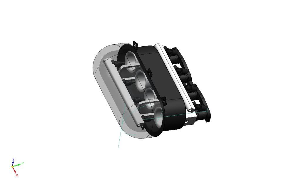
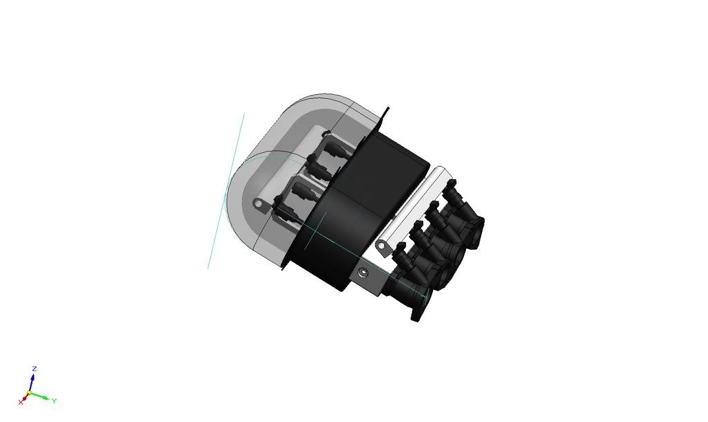
Ok so a couple of things to note are, obviously they aren't finished ie its just the basic in there.
Secondly they are being built to a budget, with the emphasis of ease of manufacture and cost, As i am making them for myself out of my own back pocket so these two things are important, so I realise it will be compromised somewhat, but I still feel it is an improvement over a stock IM. It has been designed for n1 cams, maybe slightly bigger.
It is 330mm from valve to end of trumpet. It is 380mm horizontally from the flange face to the outer most edge of the air filter (dont know how this would fit in a fwd car as mine is going in a rwd car.
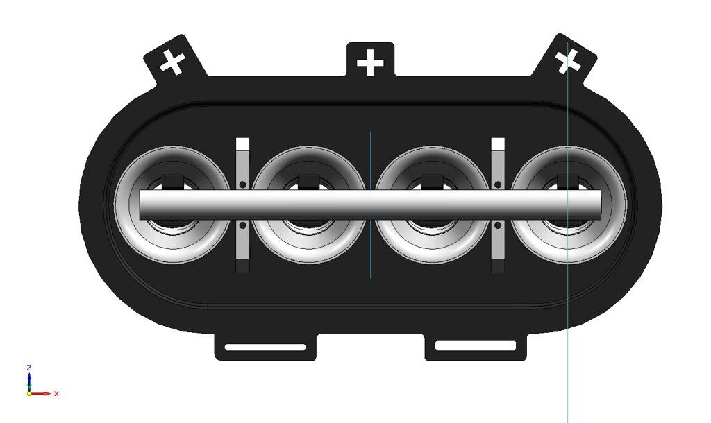
The manifold is cut 5 mm past the injector bosses and flanges are welded on. The Blocks that bolt to the flanges are CNC machined and transitions from the oval port (34mmX52mm from memory) of the factory intake to a 45mm butterfly. They are Jenvey Trumpets (which I already have) and stand off injectors (mounting and plumbing not finished)
As I said They are not entirely finished but I would love some constructive critism from you guys in the know.

Cheers
Nick


Edit: When I go back into work in a couple of days i'll get a section view of the block showing the transition, this is the part I feel is most compromised
+ Reply To Thread
  • [Type to search users.]
  • Quick Reply
    Thread Information
    There are currently ? users browsing this thread. (? members & ? guests)
    StubUserName

    Back to top