
Originally Posted by
supercowboy  Is there a data log of this run I would like to see this.
There probably are plenty of data logs. The laptop with them is gone forever though, so I won't be able to show them. :-(
Originally Posted by
supercowboy First off in this map why not rescale this map and get rid of th "grey area" not being used.If you're talking about the VEMS map, it's because I was planning on tuning the boost section once I added the turbo, and I did.
If you're talking about the AEM map, it's because we were turning up the boost daily and had no idea where we'd stop. Same for the rpm range. We planned on going higher.
Originally Posted by
supercowboy remember when it goes to the end of the map it will not fall off the map it will have that same number even if it exceeds the load or rpm.That may be how the daughter boards work, but I haven't looked that hard into AEM and what it does when you leave the map. Are you sure it holds the value of the last cell? I figured it did something similar to VEMS, which takes the last two values in the map and creates a line that follows that trend on forever. Again, AEM's maps are so large I haven't worried about it.
Originally Posted by
supercowboy Aem maps are very generic. Most of them dont work properly and need many adjustments.I'll have to take your word for it. From what I've seen they are not generic at all. They are specifically for stock applications, and specifically safe. If you try to use them on something else, obviously you have some playing to do.
How many AEM base ignition maps have you used on bone stock applications?
Originally Posted by
supercowboy I would start my map looking something like this. this is just a generic map.
http://img.photobucket.com/albums/v103/supercowboy/stockmap.jpg
Notice my scaling of the kpa and rpms. Yes the map sensor is a 3.5 bar but I dont need to use the values that exceed 25 psi. This way the map will allow for better resolution in lower rpms. This helps for drive ability. I would much rather see the area under boost have lower resolution this way it will stay in the area and be solid timing numbers.
I always make so I can control them not the other way around.
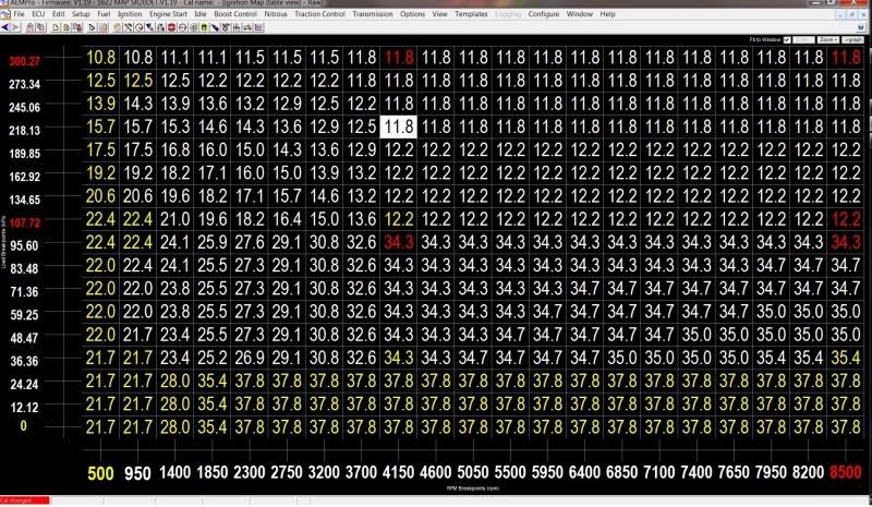
You're preaching to the choir here. I guess I'll post up my current timing map. I think it's current anyway. I could have sworn I had less timing in the 170 kPa area, but I guess I didn't have as little as I thought. (Unless the map on my car is newer. I will have to check).
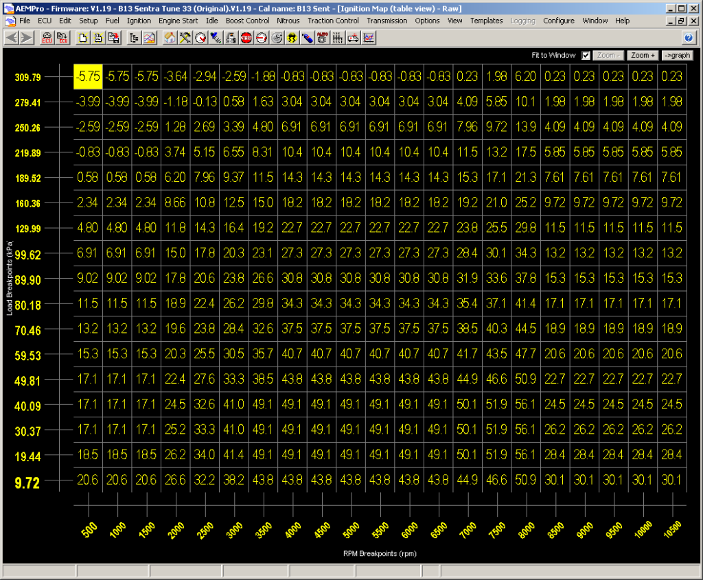
I too took the pressure scale on the left and modified it to fit my needs. I like a lot of resolution in the vacuum section, so I have the pressures go in 10 kPa increments. Then once in boost I start going with 30 kPa increments because I don't need much resolution in boost. I don't go all the way up to 350 kPa either (even though I have a 3.5-Bar MAP sensor).
I haven't scaled the rpm like you have. I didn't find the need to really. I can see why it would be beneficial and I might try it in the future, but since the car idles great and the air/fuel ratios don't have any issues between cells I haven't found much need to modify the rpm scale. (Obviously anything past 8,000 rpm is untuned and stupid retarded on purpose.)
I thought I had 13 degrees of timing at 170 kPa (10 psi) but it looks like I have 16.9 (call it 17) degrees there at torque peak (5,500 rpm). Not sure how you feel about that...
If you see where I am at 100 kPa (0 psi) and where I am at 170 kPa (10 psi) you'll see I'm removing about 1 whole degree for every 1 psi above atmospheric. Honestly, I thought I was removing more. I'm going to double check the map actually loaded in the ECU. It will probably be the same though. =/
Originally Posted by
supercowboy You can always add timing, but when you have too much to start you can have worse failures. You should always data log and see where the timing is moving to. Especially on the street where you dont have much control.With some ECUs where you don't have total control over the the timing then it makes sense to log it always. I've found there isn't much need with AEM to log timing on a regular basis because it does what you tell it to without doing anything tricky if you know what you're doing. If I'm going to tune timing (instead of fuel) obviously I'd recommend logging it.
")
I have plenty of logs of my tune I believe with timing logged as well that we could look at if we want. And I can take the car and check timing at high rpm with the timing light if you insist.


 Be the first to like this post.
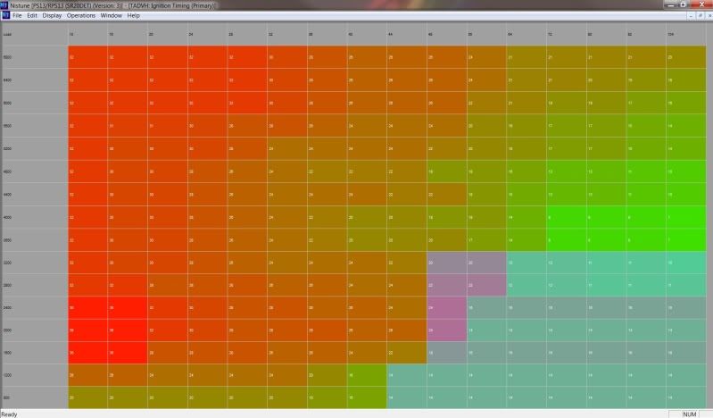
")


