I will be writing this over the course of the next few weeks. Here is an outline and a list of supplies to start off.
- MK3 Toyota MR2 Power Steering Pump
- Schematics www.mazdaspeedy.com: Toyota MR-S Electric power steering pump conversion
- Custom hoses
- 8 AWG Cable
- 50 Amp Fuse
- 50 Amp Relay
Here are some pictures of the pump I will be using.
The MK3 Pump is an all in one design where previous generations had 3 pieces; Reservoir, Pump and ECU.
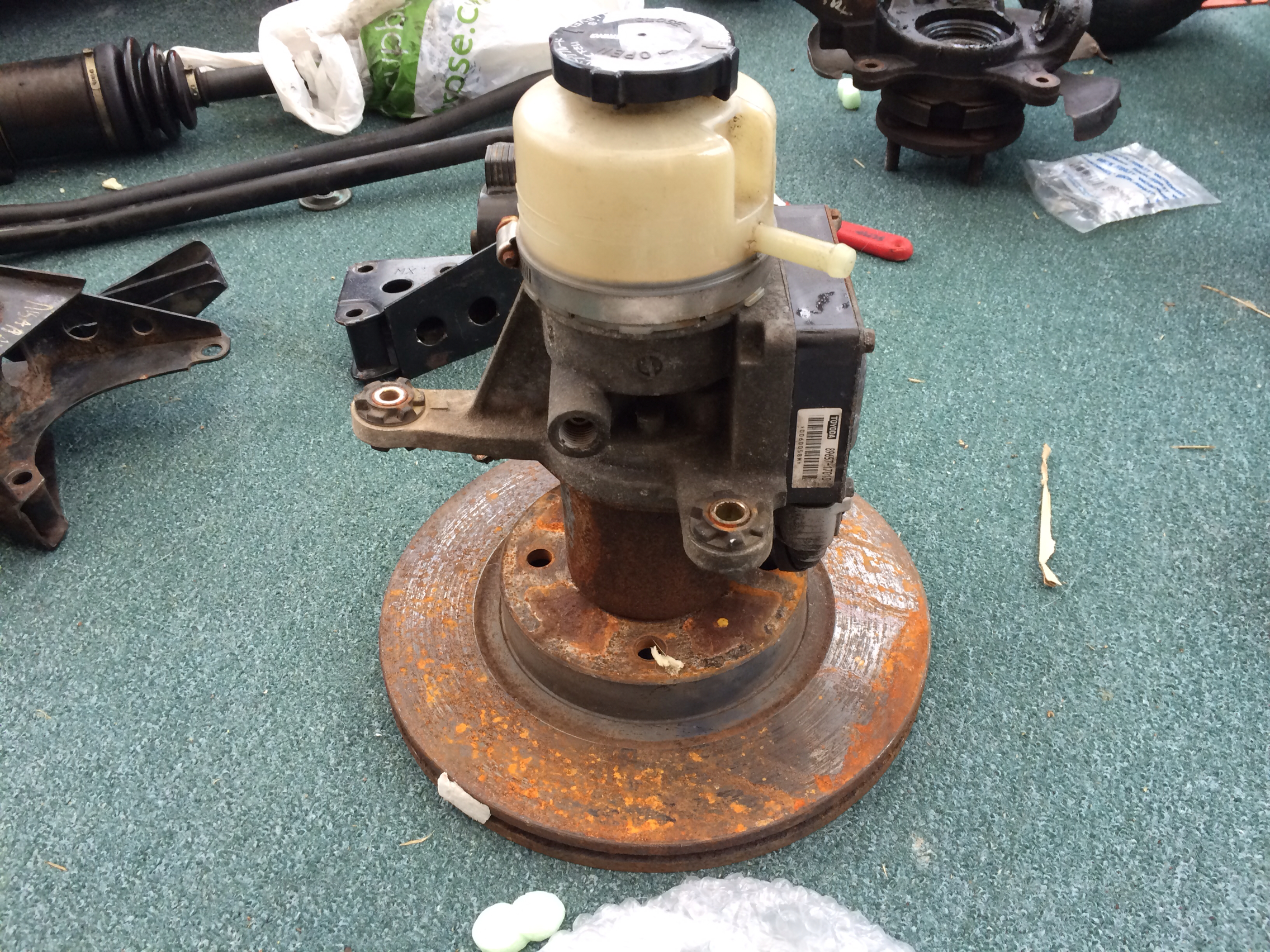 PS Pump by Mattick22, on Flickr
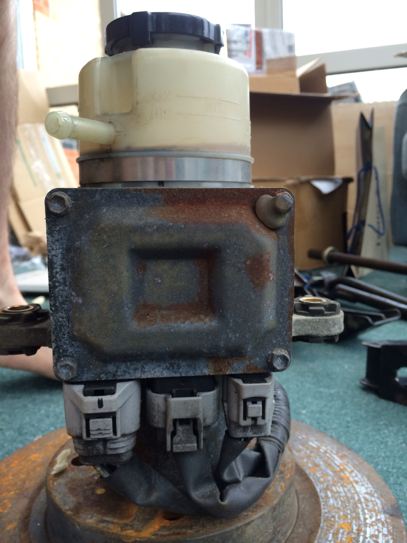 PS Pump by Mattick22, on Flickr
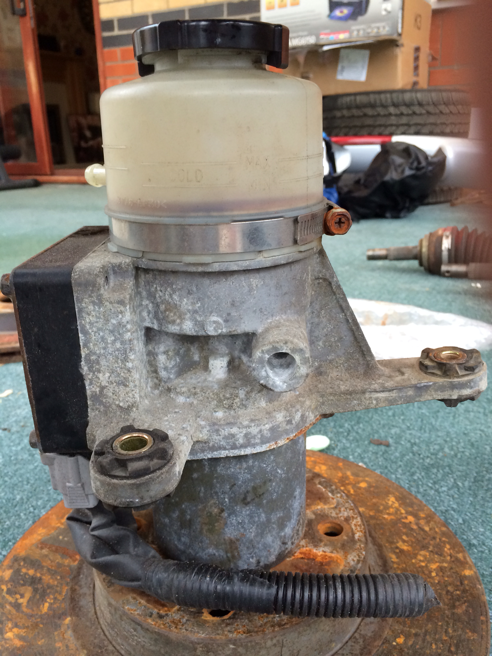 PS Pump by Mattick22, on Flickr
Here is the wiring diagram for the pump that I will be using for the install. Some have used a 40amp circuit but I am going to stick with whats on the schematic.
 attachment.php by Mattick22, on Flickr
I will also be converting to an electric water pump so I will only have the alternator belt. This mean that my wiring will be a bit different and I also have relocated my battery to the back seat area.
I am doing this mod as I hate the location of the current power steering pump, switching to an electric water pump, but I still need power steering for being in the UK. That and I have a bad shoulder so I would want it anyway. In theory it should deliver the convenience of low speed maneuverability with a more direct to rack Will it produce more power? It only draws 3-5 amps at idle and with the speed input it "idles" during straight line driving. So maybe, yes a bit more power and maybe a fraction more MPGs but they are not the reasons to do this.
My local hydraulic shop cut me a meter of line and some miscellaneous 3/8" fittings and adapters to see what will work. I am hopping I went long on the line so I can secure it out of the way. I am planning to mount it in the same region that the old one would be.
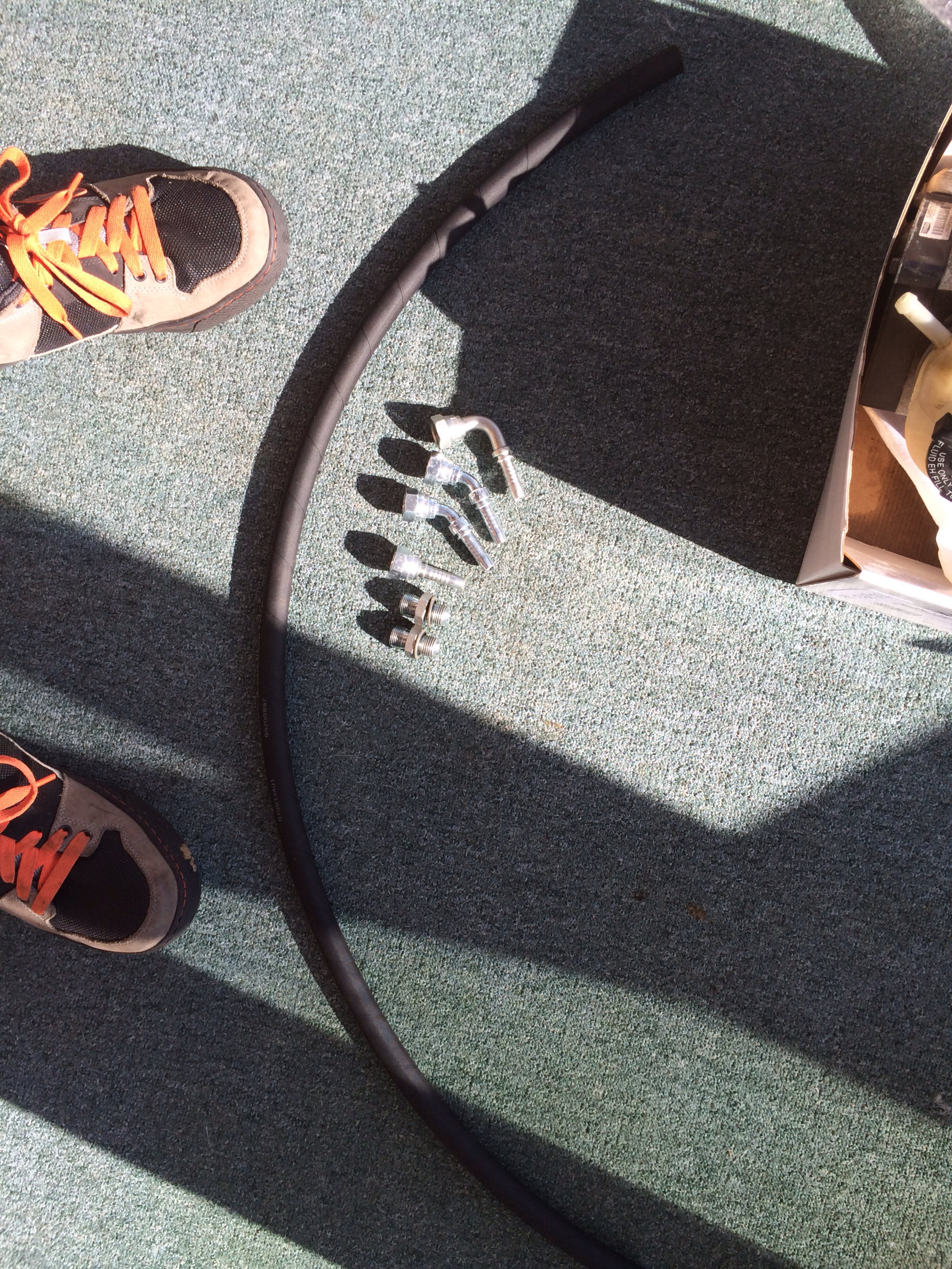 PS hose by Mattick22, on Flickr
Some of the tools you will need:
10mm socket & wrench
12mm socket & wrench
14 ...if you have worked on your Nissan before you know the drill...
2x Flat screw drivers
Rubber Mallet
Gloves
Drain pan
Rags
But you will need a 14mm line wrench. You will need a 14mm line wrench...
Thats this thing...
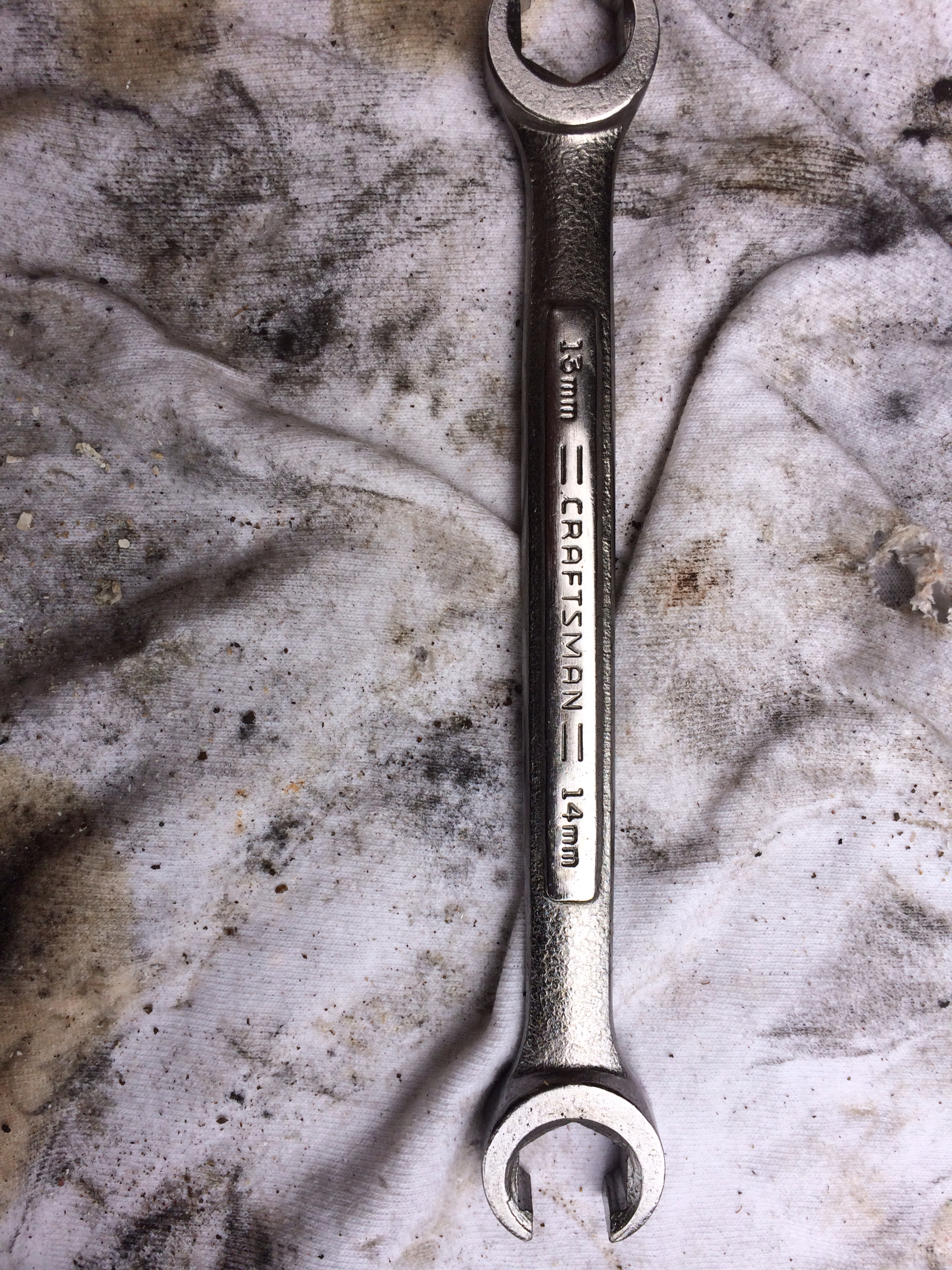 Ps by Mattick22, on Flickr
Removal of the old system
We wil be removing the old lines, pump, pump brackets, reservoir and reservoir brackets.
Some of the pictures will be show of a motor that outside the engine bay, this is for clarity of the photos. I am doing the same thing with the motor in the car (B14).
Now in effort not to be condescending I will mainly focus on the overall and not so much the detail for removal as most reading this could have it off in .3 seconds compared to me.
Start by loosening the low pressure line from the rack with a 10mm socket and or wrench. Let the contents drain into the drain in the pan.
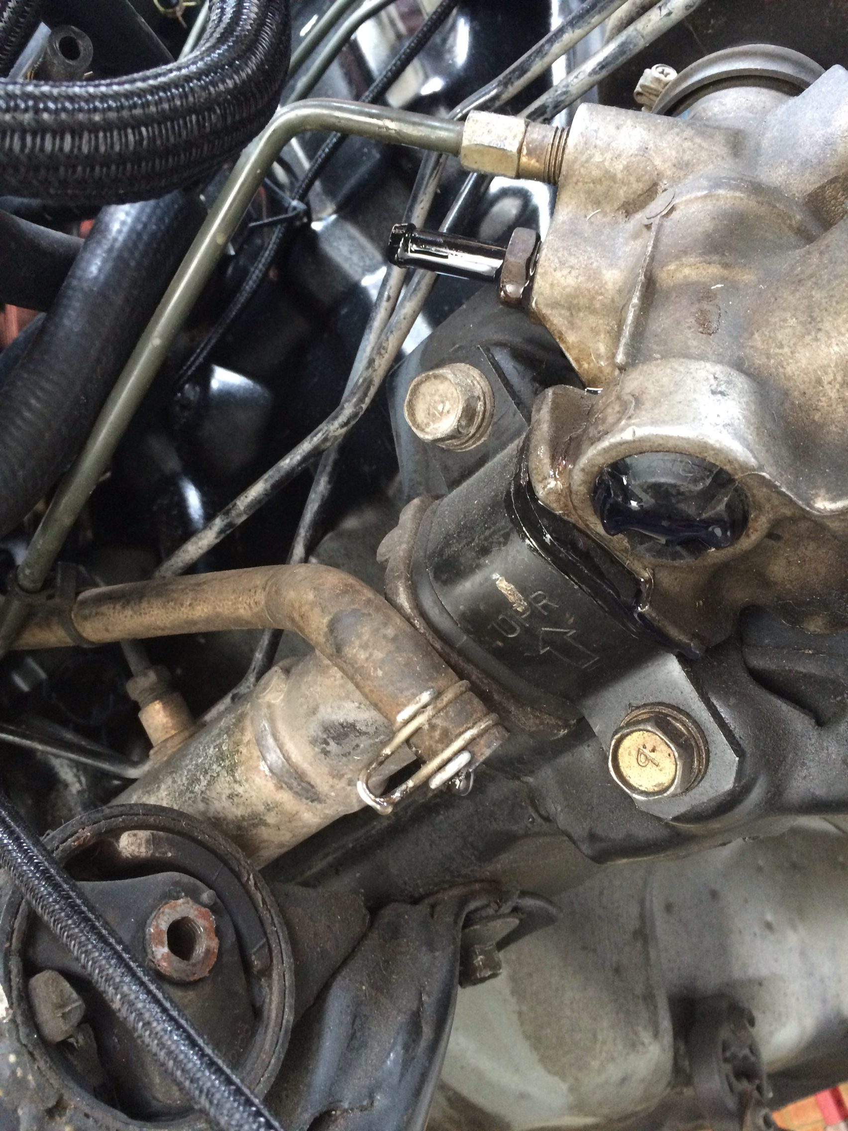 Ps by Mattick22, on Flickr
This will empty one of the compartments in the reservoir.
Take the reservoir off its bracket and tilt it so most of the fluid comes out of the low pressure side. This is just to keep things clean.
Unbolt the bracket, there should be 3 10mm bolts holding it on.
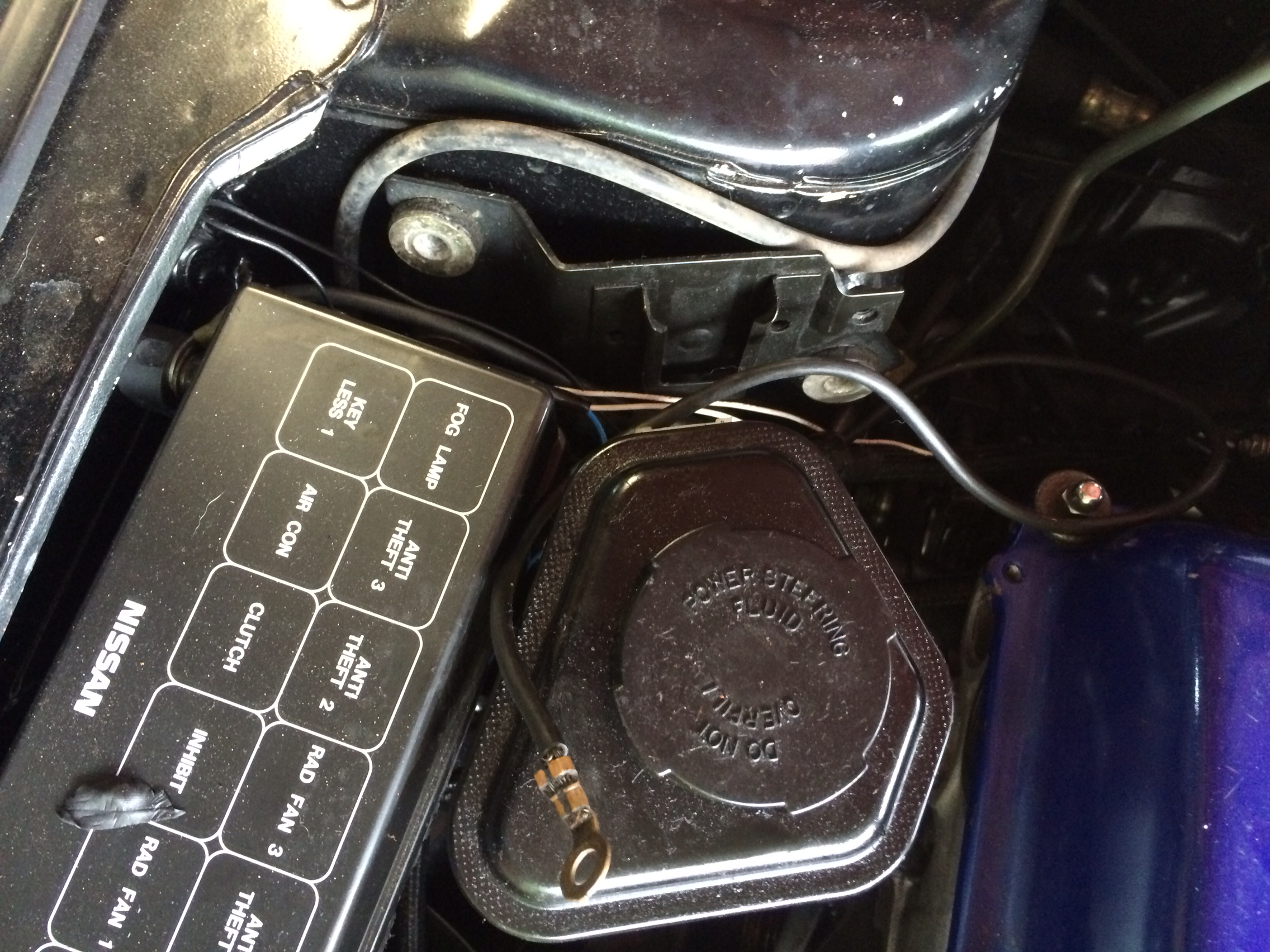 Ps by Mattick22, on Flickr
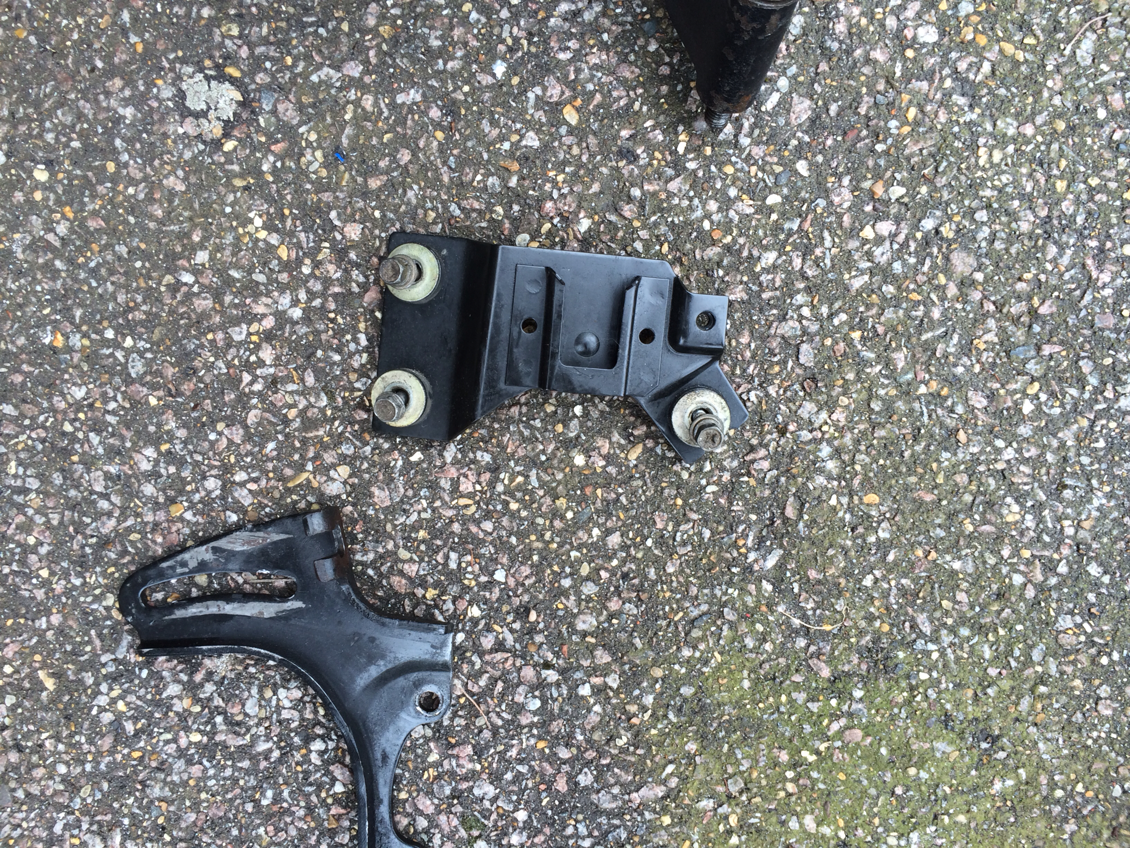 Ps by Mattick22, on Flickr
Use the 14mm line wrench to unscrew the high pressure line at the rack and then the pump.
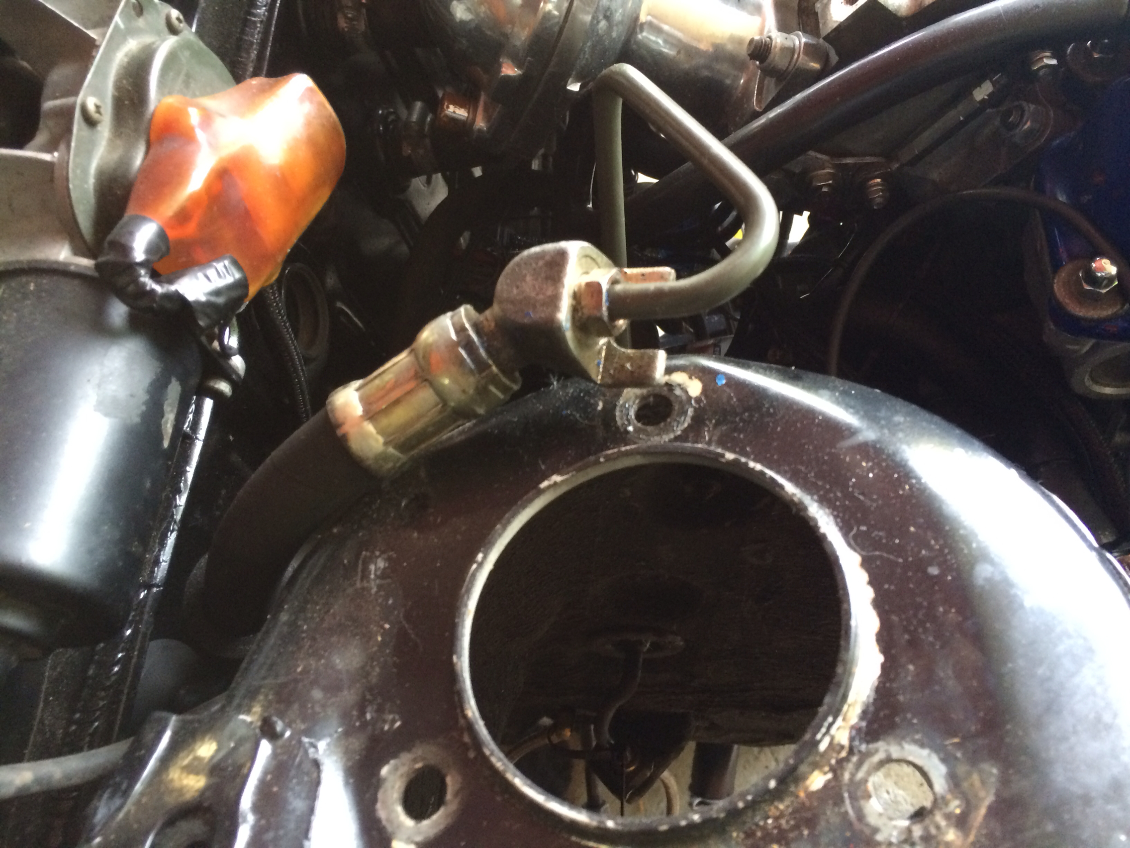 Ps by Mattick22, on Flickr
Let contents drain.
Loosen hose clamps on reservoir and remove. Then remove the bracket securing the lines to the passenger side frame rail
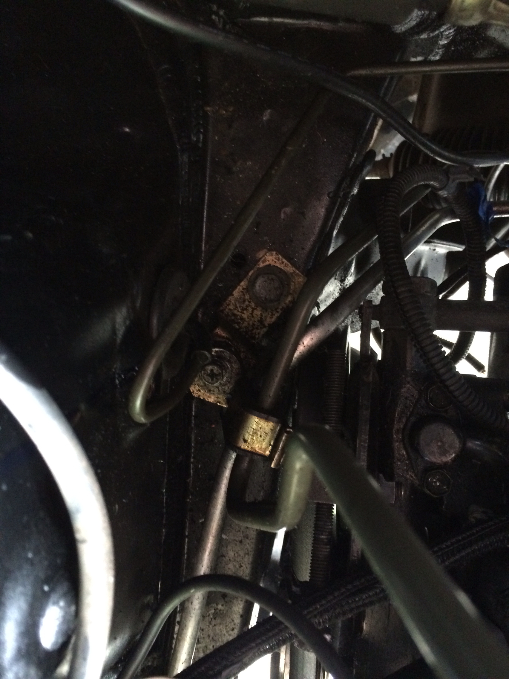 Ps by Mattick22, on Flickr
You are now ready to remove the pump.
Loosen the tensioner bolt, remove belt. Remove the water pump pulley as well. This may require you to pry the motor towards the drivers side a bit to get the pulley out. This is to get to the 2 10mm bolts holding the tensioner rail-frame-a-ma-jig.
Now snake out the pump and post in classifieds for $5 plus shipping...
Your area should look like this now.
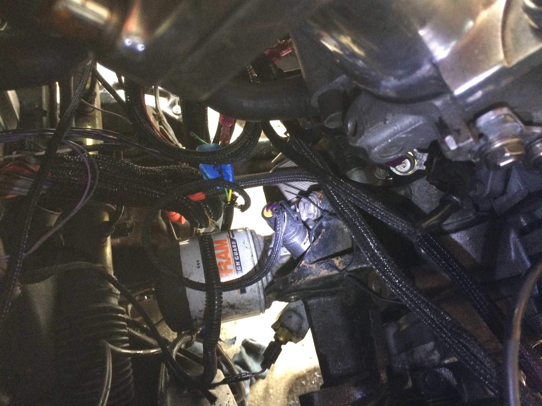 Ps by Mattick22, on Flickr
See the illuminated bolt? Its a 14mm and a bitch if you have aftermarket oil temp senders. There are three bolts holding that on as well.
Here is a pic of the block with all PS related items removed
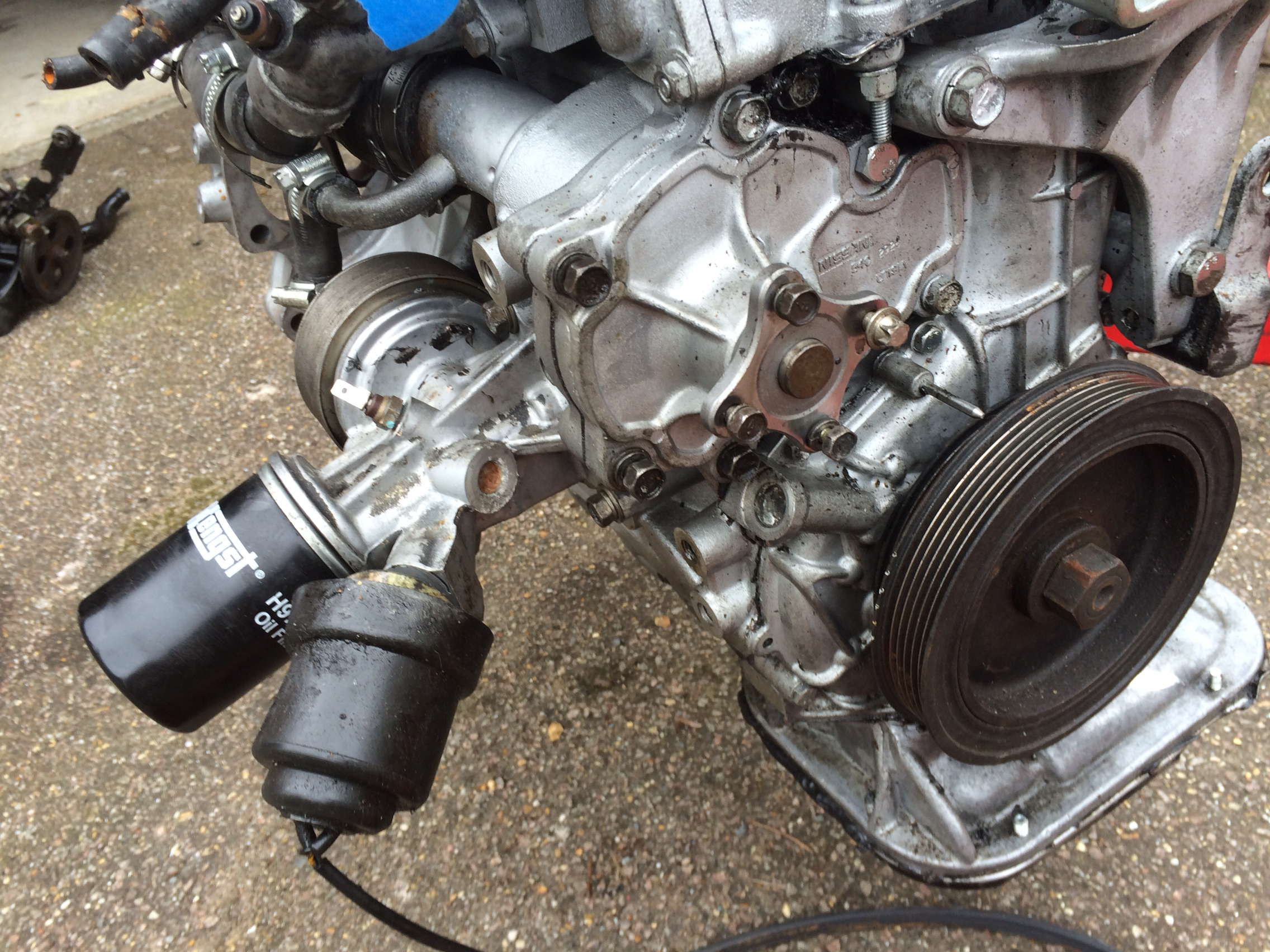 Ps by Mattick22, on Flickr
The only thing holding the lines in right now is this bracket.
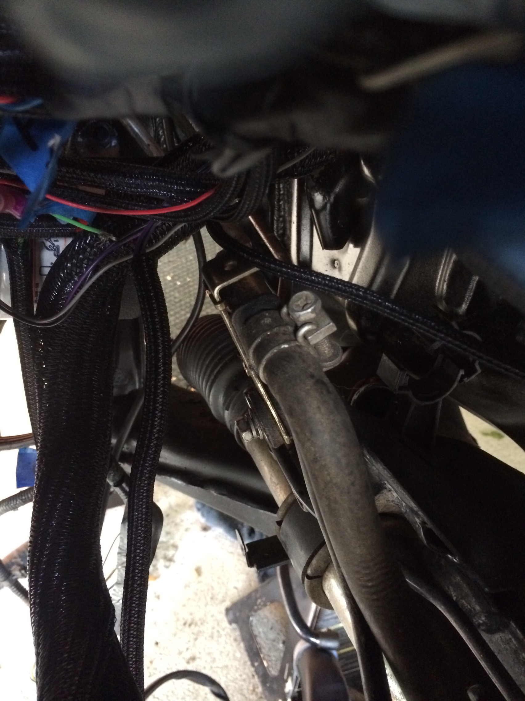 Ps by Mattick22, on Flickr
Remove the 10mm bolt and snake the lines up from the top.
Now turn your attention to the new pump. Do not be tempted to try and clean it up by removing the bottom motor case...
(This write up may be delayed... I may have broke it...)
Instead remove the plug and loom if they came with the pump, chances are there is corrosion in there. I used 2 flat head screwdrivers to help me wiggle them off.
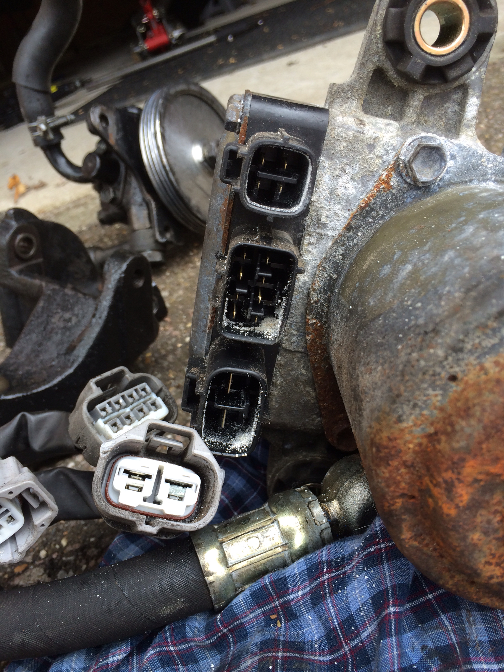 Ps by Mattick22, on Flickr
Use some electrical cleaner to remove the corrosion in the plugs.
I caution you on this next step. Be very gentle, the reservoir may be more brittle than you think...
Remove the large worm gear clamp holding the reservoir on.
 PS Pump by Mattick22, on Flickr
Use the flat head screwdriver and rubber mallet. Place the screwdrivers blade under the top lip of the channel used for the clamp.
Gently, rotating around the reservoir tap the screwdriver with the mallet to remove it.
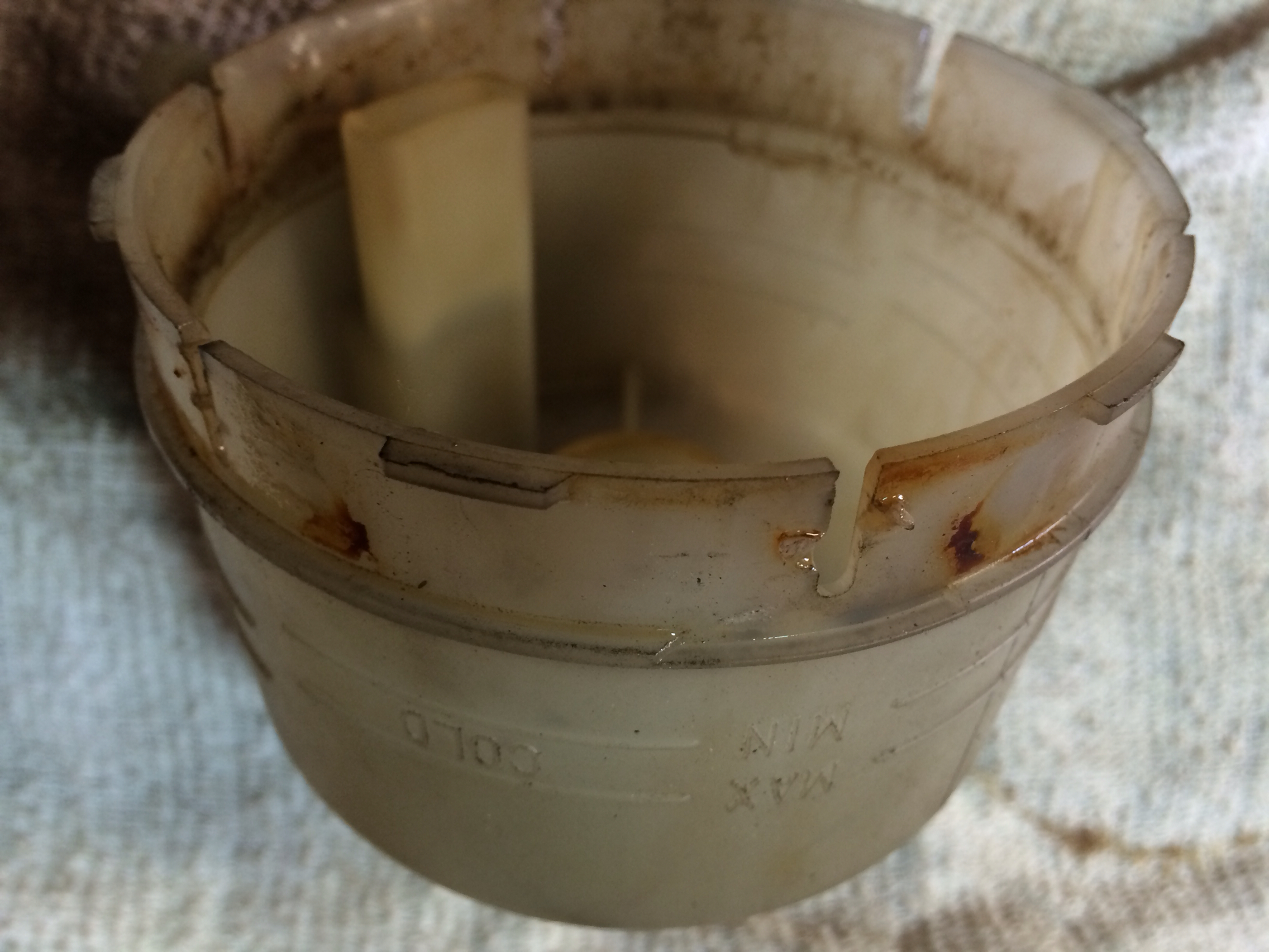 Ps by Mattick22, on Flickr
Clean off any corrosion around the clamping area.
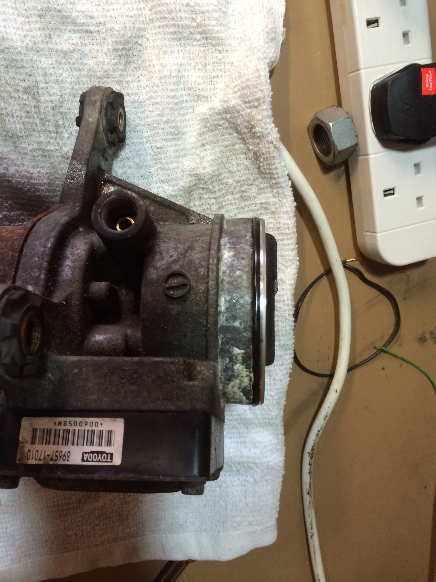 Ps by Mattick22, on Flickr
Now place a glove or other wise mask off the opening to the pump.
Snake up the pump from underneath the vehicle and go up and over the oil filter assembly. Now I also don't have any suspension on so I am not sure how easy that part will be for those still on the road. Allot some time for those additional steps.
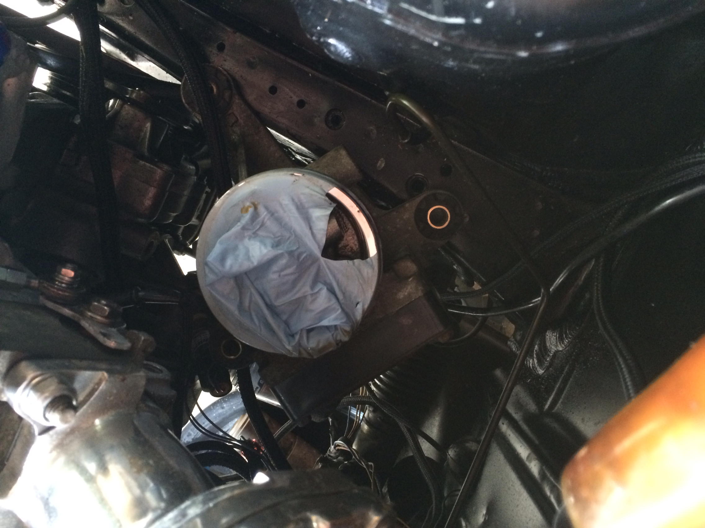 Ps by Mattick22, on Flickr
With the ECU facing the firewall this is where we (I) will begin tempting for a mount to be made.
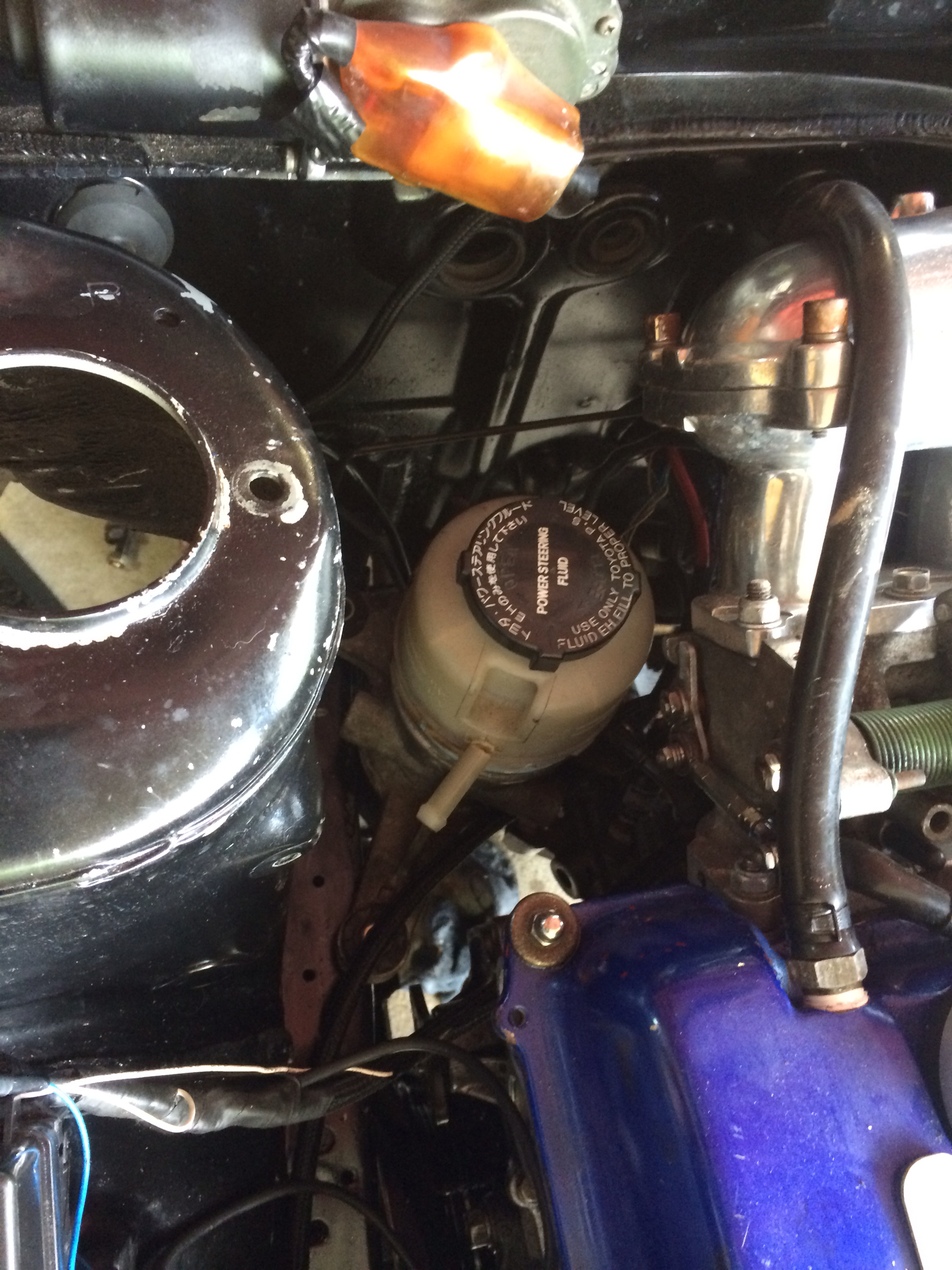 Ps by Mattick22, on Flickr
I may raise it up a bit to allow better access to the fluid.
Also don't do this...
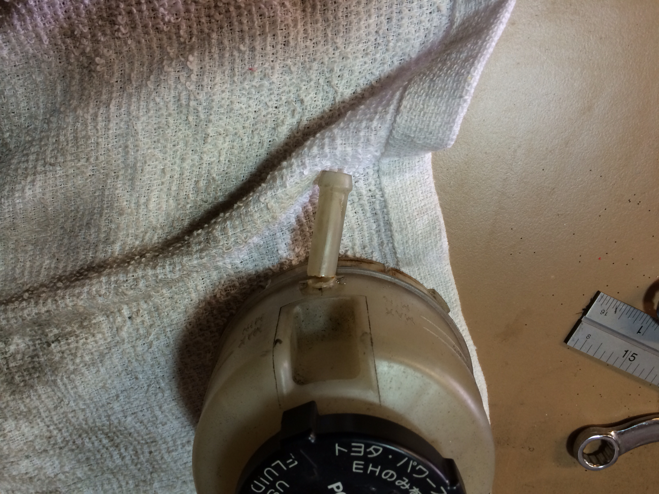 Ps by Mattick22, on Flickr
Until Next Time...
TBC
- MK3 Toyota MR2 Power Steering Pump
- Schematics www.mazdaspeedy.com: Toyota MR-S Electric power steering pump conversion
- Custom hoses
- 8 AWG Cable
- 50 Amp Fuse
- 50 Amp Relay
Here are some pictures of the pump I will be using.
The MK3 Pump is an all in one design where previous generations had 3 pieces; Reservoir, Pump and ECU.
 PS Pump by Mattick22, on Flickr
 PS Pump by Mattick22, on Flickr
 PS Pump by Mattick22, on Flickr
Here is the wiring diagram for the pump that I will be using for the install. Some have used a 40amp circuit but I am going to stick with whats on the schematic.
 attachment.php by Mattick22, on Flickr
I will also be converting to an electric water pump so I will only have the alternator belt. This mean that my wiring will be a bit different and I also have relocated my battery to the back seat area.
I am doing this mod as I hate the location of the current power steering pump, switching to an electric water pump, but I still need power steering for being in the UK. That and I have a bad shoulder so I would want it anyway. In theory it should deliver the convenience of low speed maneuverability with a more direct to rack Will it produce more power? It only draws 3-5 amps at idle and with the speed input it "idles" during straight line driving. So maybe, yes a bit more power and maybe a fraction more MPGs but they are not the reasons to do this.
My local hydraulic shop cut me a meter of line and some miscellaneous 3/8" fittings and adapters to see what will work. I am hopping I went long on the line so I can secure it out of the way. I am planning to mount it in the same region that the old one would be.
 PS hose by Mattick22, on Flickr
Some of the tools you will need:
10mm socket & wrench
12mm socket & wrench
14 ...if you have worked on your Nissan before you know the drill...
2x Flat screw drivers
Rubber Mallet
Gloves
Drain pan
Rags
But you will need a 14mm line wrench. You will need a 14mm line wrench...
Thats this thing...
 Ps by Mattick22, on Flickr
Removal of the old system
We wil be removing the old lines, pump, pump brackets, reservoir and reservoir brackets.
Some of the pictures will be show of a motor that outside the engine bay, this is for clarity of the photos. I am doing the same thing with the motor in the car (B14).
Now in effort not to be condescending I will mainly focus on the overall and not so much the detail for removal as most reading this could have it off in .3 seconds compared to me.
Start by loosening the low pressure line from the rack with a 10mm socket and or wrench. Let the contents drain into the drain in the pan.
 Ps by Mattick22, on Flickr
This will empty one of the compartments in the reservoir.
Take the reservoir off its bracket and tilt it so most of the fluid comes out of the low pressure side. This is just to keep things clean.
Unbolt the bracket, there should be 3 10mm bolts holding it on.
 Ps by Mattick22, on Flickr
 Ps by Mattick22, on Flickr
Use the 14mm line wrench to unscrew the high pressure line at the rack and then the pump.
 Ps by Mattick22, on Flickr
Let contents drain.
Loosen hose clamps on reservoir and remove. Then remove the bracket securing the lines to the passenger side frame rail
 Ps by Mattick22, on Flickr
You are now ready to remove the pump.
Loosen the tensioner bolt, remove belt. Remove the water pump pulley as well. This may require you to pry the motor towards the drivers side a bit to get the pulley out. This is to get to the 2 10mm bolts holding the tensioner rail-frame-a-ma-jig.
Now snake out the pump and post in classifieds for $5 plus shipping...
Your area should look like this now.
 Ps by Mattick22, on Flickr
See the illuminated bolt? Its a 14mm and a bitch if you have aftermarket oil temp senders. There are three bolts holding that on as well.
Here is a pic of the block with all PS related items removed
 Ps by Mattick22, on Flickr
The only thing holding the lines in right now is this bracket.
 Ps by Mattick22, on Flickr
Remove the 10mm bolt and snake the lines up from the top.
Now turn your attention to the new pump. Do not be tempted to try and clean it up by removing the bottom motor case...
(This write up may be delayed... I may have broke it...)
Instead remove the plug and loom if they came with the pump, chances are there is corrosion in there. I used 2 flat head screwdrivers to help me wiggle them off.
 Ps by Mattick22, on Flickr
Use some electrical cleaner to remove the corrosion in the plugs.
I caution you on this next step. Be very gentle, the reservoir may be more brittle than you think...
Remove the large worm gear clamp holding the reservoir on.
 PS Pump by Mattick22, on Flickr
Use the flat head screwdriver and rubber mallet. Place the screwdrivers blade under the top lip of the channel used for the clamp.
Gently, rotating around the reservoir tap the screwdriver with the mallet to remove it.
 Ps by Mattick22, on Flickr
Clean off any corrosion around the clamping area.
 Ps by Mattick22, on Flickr
 Now place a glove or other wise mask off the opening to the pump.
Snake up the pump from underneath the vehicle and go up and over the oil filter assembly. Now I also don't have any suspension on so I am not sure how easy that part will be for those still on the road. Allot some time for those additional steps.
 Ps by Mattick22, on Flickr
With the ECU facing the firewall this is where we (I) will begin tempting for a mount to be made.
 Ps by Mattick22, on Flickr
I may raise it up a bit to allow better access to the fluid.
Also don't do this...
 Ps by Mattick22, on Flickr
Until Next Time...
TBC
Last edited by Mattick22
on 2014-05-31
at 13-17-33.


 Back to top
