How I did it.
First, a warning. I will take no responsability for what you decide to do to your car. If you do not know how to fabricate, do not do this yourself. Do not ask me to do this mod to your car as I will have to decline (I do not enjoy working on other people's cars). If you do not know how to weld, do not do this yourself. I will post enough info here that you should be able to take it to a good fabricator and they will be able to figure out what to do.
I will be more than happy to answer any questions you may have about the conversion process. That is why I am posting here on the forum for everyone to see.
Remember, this is my version of how to install a panhard bar on a B-14. My hope is that it may inspire someone else to come up with thier own version that may be better than mine. At the very least I hope that this can become an invaluable reference to anyone who is even mildly interested in a panhard bar conversion as the info up to this point has been a bit elusive.
Now to the why, as in, why did I decide to do this conversion. Well, a couple of months ago I took the SE-L to Sebring for a track day. In case you did not know, Sebring is known for being a bumpy track, especially in turns 1 and 17. It was in these turns that I noticed something funny. The car acted very oddly. It was like the front end of the car and the back end of the car were not connected. Each end went through the turns in it's own way. This was not a very comfortable feeling especially in turn 1 which is a high speed (80mph+) blind left hander. I knew instantly that the Scott-Russell Linkage (SRL) was to blame as I had read about it previously (thank you Mike Kojima). I knew that this had to change before I went to another track day.
My setup;
280,000+ mile chassis
KYB AGX front struts/rear shocks
Road Magnet progressive rate springs
Progress adjustable front sway bar
Progress rear sway bar (non adjustable)
Stillen FSB
Generic RSB
SR20VE with N1 cams
B-15 5speed VLSD(with terabley vague shifter, blah!)
SSAC header (I think) with 2.5" collector
Hodge-Podge exhaust that ends with 2.25" piping to a Subaru STI muffler (wtf? )
All of this stuff was on the car when I bought it.
For the track day I was using 15x7 +35 wheels with Continental Tire slicks (one heat cycle take-offs from one of the Continental Tire Challenge Mini race teams)
For the street I use 17x7.5 +40 with Yokohama S-Drives that are currently very worn.
The reseach I did consisted of searching Google for B-15 panhard bar. I am not going to post all of those links because it will be easier for you to open another browser page, go to Google and do your own search. I found a lot of stuff from 2J Racing Shop. Mike Kojima's Moto IQ article on his B-15 race car was also a great source of info, i.e. photo insperation.
There is one link I will post,
RPM Net Tech Articals: Understanding Coil Springs - Powered by: AFCO
If you are considering this panhard bar conversion, go to that link and save it in your favorites right now! If you read it and don't understand it, read it again. And again. And again! I have read it several times. It is good stuff.
As far as fabrication goes, it probably took me about 16 hours over 4 days. This was all done in my driveway with basic fabrication tools;
4.5" grinder
sawsall
drill press
cordless drill
Millermatic 211 wire feed welder (GMAW-S, Agon/CO2)
tape measure
silver pencil
sharpie
speed square
and all of the required PPE, because I hate having shards of metal in my eye!
I will not rate the fabrication on a scale of 1-10 because I have been fabricating professionially since 1996. So my scale may be different than your scale. I did not consider any of this to be very difficult, but it does take some time.
We will get to the nitty gritty in the next post!



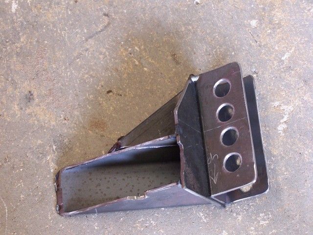
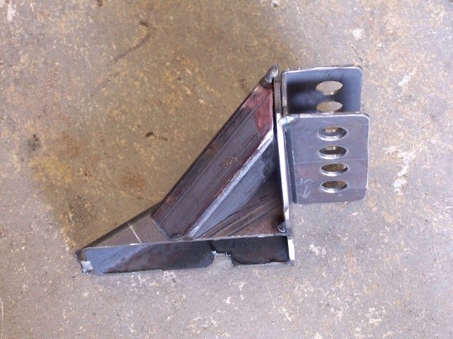
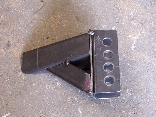
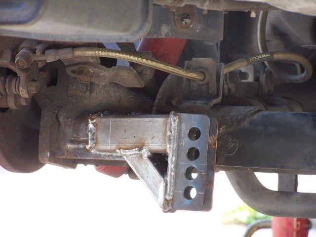
 Back to top
