Welcome to the SR20 Community Forum - The Dash.
Register
SR20 forum logo

Thread: Prepping for MAP conversion

+ Reply To Thread
Posts: 11-20 of 101
2013-05-05 13:48:53
#11
Originally Posted by lynchfourtwenty
another thing, in this link

but it doesn't mention the green wire in the picture, which is going to the outward ground for the map sensor.. i grounded my map sensor to the strut tower, i used a tester around the bay and it seemed as good place as any..

should i change this? should i ground the breakout to the same location as the ecu grounds and then ground the map sensor to the breakout? or will it be ok as is?


You can ground the MAP sensor to the ADC box if you would wish, that isn't a problem.
2013-05-05 19:26:18
#12
awsome guys!!

does the adc box need a ground at all if im using other grounds for my map/iat?
2013-05-06 00:51:50
#13
Ok, So there are a TON of ways to wire up a MAP and IAT sensor..

Here's what i found..

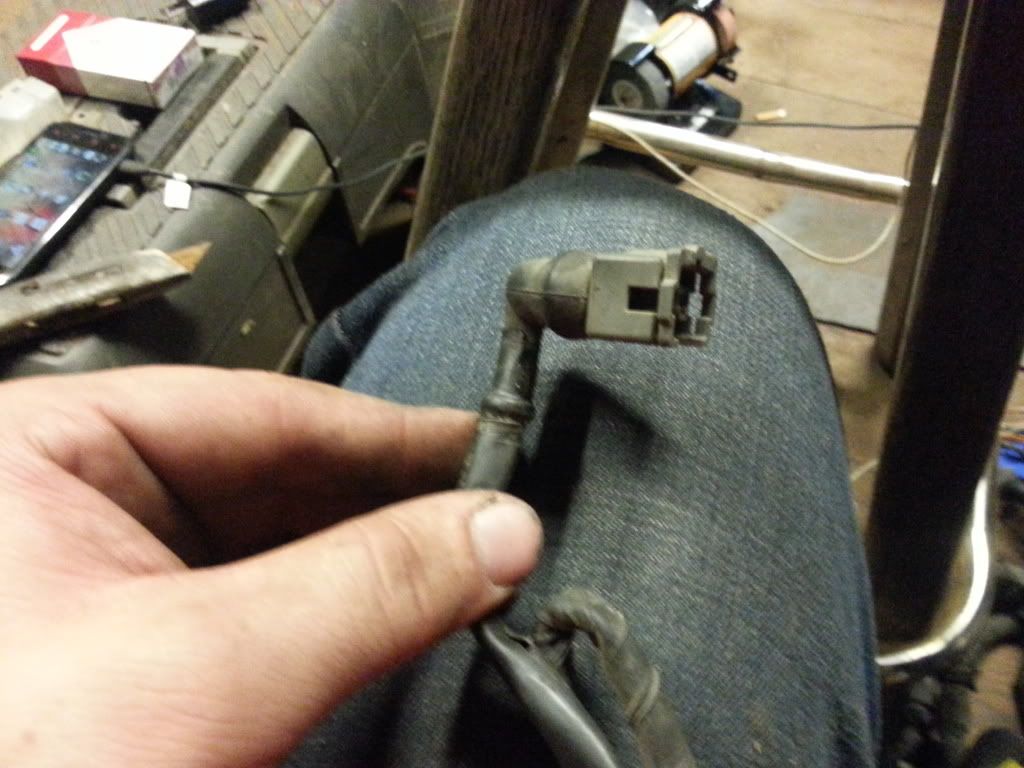
blue w/ yellow strip pin 8 EGT sensor
black 21 or 29
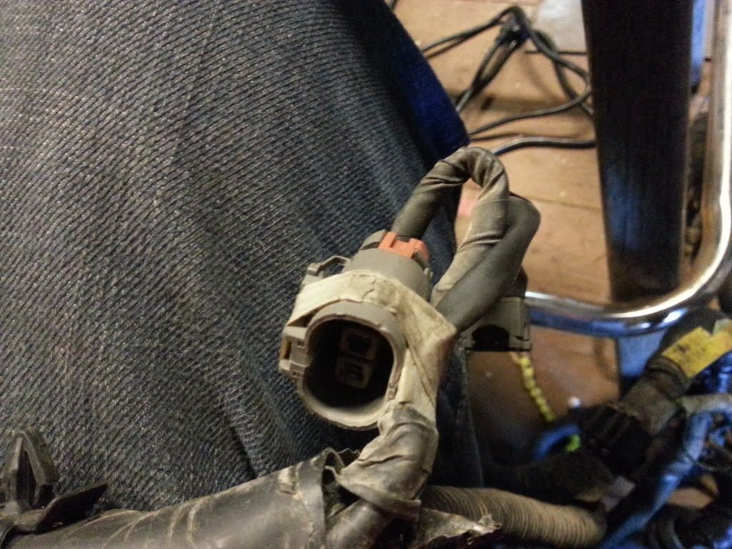
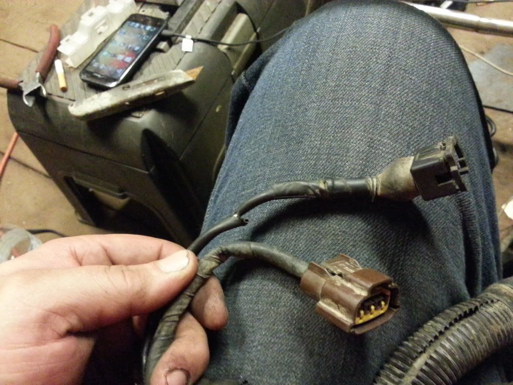
this plug is located near the "AIV" plug by the #4 injector plug


pink AIV solenoid pin 102
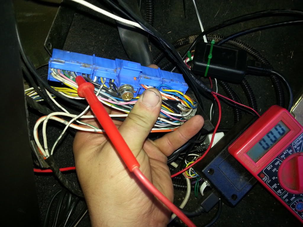
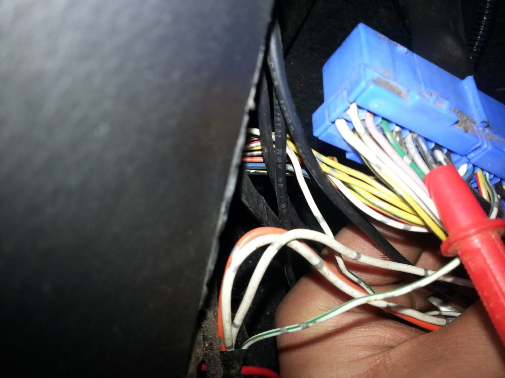
white w/ green stripe goes to under dash plug
this plug is located near the "EGT sensor" plug by the #4 injector plug


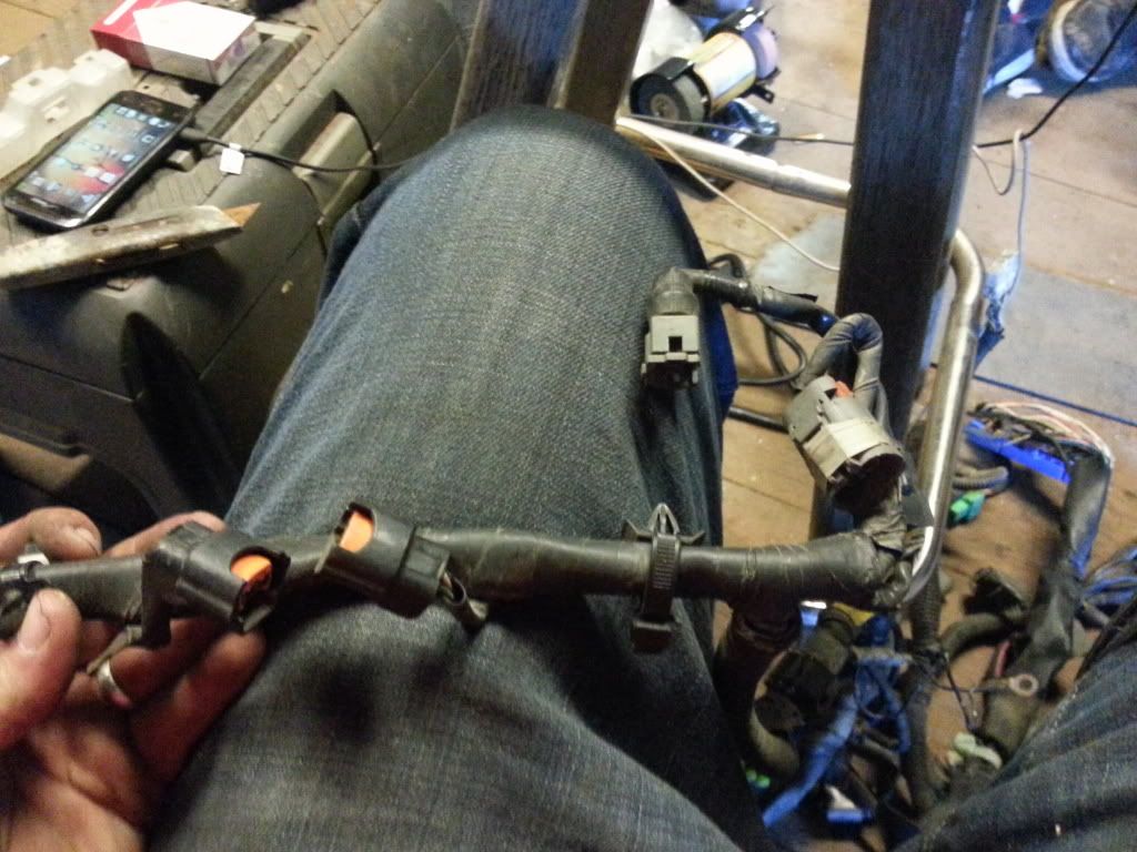
grey EGR and canister control solenoid pin 105
white w/ green strip also goes to under dash plug


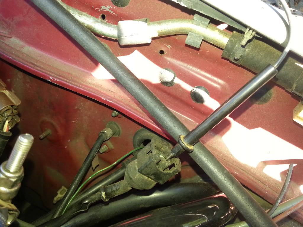
This plug is located right next to the tps plug..


Your probably like, whats with the white wire w/ green stripe.. truth is i have no freaking clue, both the "AIV" and "EGR & Canister control solenoid" plugs have a white and green wire, the must connect somewhere and they lead to he big white under dash plug.. after that i have no idea where they go but with the dash plug connected i get a ground at pin #6 on the ecu plug which is a ground, if i unplug the white plug i get nothing at the ecu at all.. so its def a ground.. its odd tho it dont read 0.00 on the meter like the other ones, it reads 0.08 so maybe theres a resistor in place?


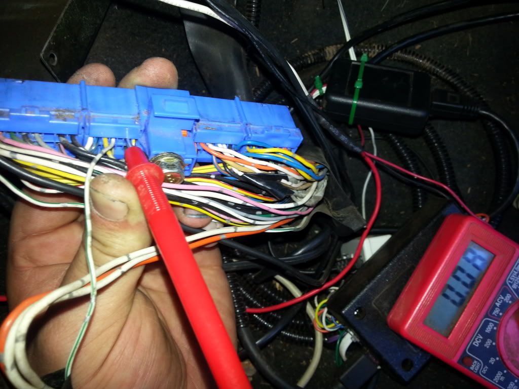
So what i am doing is using the "AIV" and the "EGR & Canister" wires, they were in the right spot and all that, so the white w/ green stripe was made a ground since it was anyways..

For the IAT i am using the grey wire (cut it from ecu plug) to goto the ADC box for signal..

Then for the map im using the "AIV" wiring, so again white an green went to ground, pink is signal wire (cut it from ecu plug) and got routed to ADC box, then just ran a 5v out from ADC box to sensor..

I haven't finished the IAT sensor wiring, i need a resistor i guess to complete it..

Heres a pinout for reference..


I was able to cross reference and double check on a spare harness, so im pretty comfortable stating this for a 91-92 b13 se-r.

i'll report back when its all complete lol
Last edited by lynchfourtwenty on 2013-05-06 at 05-55-51.
2013-05-06 05:59:50
#14
will this resistor work?

NTE 5WR250 5W Silicone-coated Wirewound Resistor 5K Ohms | RadioShack.com

or would this be better?

http://www.radioshack.com/product/index.jsp?productId=2062329

and could i get a pic of how you guys wire them up? kinda confused lol.. the pic in this link is helpful but im not understanding where to run the resistor. do i connect 5v to one side then adc to the other then to the iat?
Last edited by lynchfourtwenty on 2013-05-06 at 10-12-41.
2013-05-06 12:16:40
#15


Both are 5k1 resistors, both go from 5v to ADC with yellow wire. IAT is then wired one side to GND (the blue wire) and other to ADC (yellow wire).

I used a digital thermometer, ice water with sensor in, measure temp, write down adc voltage, then add some warm water and repeat, then i boiled some water and kept adding cold till i had a fairly good spread of numbers to work with, then filled in the gaps. You can check by graphing the numbers to check that its a smooth curve.
2013-05-06 12:22:42
#16
Oh, ive also wired Map into ADC so i can switch between maf and map for now, if i get the map working nicely then will remove the maf later. Its not like its limiting power or anything, i just want the bling of running map sensor lol, and incase someone wants me to tune a car with one down the track.
2013-05-06 19:31:09
#17
im so confused lol....

why do ya have 2 resistors in your box?

sounds like i have a lot of work cut out for me..
2013-05-06 23:44:29
#18
Ok so the white wire with green stripe does not provide a good ground. But I see no reason it cant be cut from the white plug an moved to the adc box then run a ground to the adc box

EDIT DO NOT USE THE WHITE AND GREEN WIRE!!

it some how finds its way from the white plug to the fan relay.. i cut it and my fan stopped working, honestly i dont even know if it worked since i wired it into my map sensor but i dont know for sure.. i snipped it from the map sensor and snipped it from the iat sensor and rewired it to the white plug but my fan is still not kicking on.. im going to double check a few things tomorrow but i might of fried something in the ecu or something

if i did fry something in the ecu can is there some other way of rigging the fan to come on at a certain temp utilizing nemu or adc?
Last edited by lynchfourtwenty on 2013-05-07 at 04-14-33.
2013-05-07 04:41:54
#19
Originally Posted by lynchfourtwenty
im so confused lol....

why do ya have 2 resistors in your box?

sounds like i have a lot of work cut out for me..


With one resistor like the original diagram my sensor was way out of calibration, was 105deg C with engine not running, and there would not have been any resolution left if i calibrated it like that. Putting another resistor in brings the voltage up a bit higher to the signal.

I ran a separate loom to the AIT and Map, and then wired these straight to the ADC, rather than try mess with stock wiring, and wanted to keep the maf wired in for now but be able to test and calibrate the Map sensor still.

Depends what ecu and outputs you are using, mine only has 3 outputs as its a SSS sentra ecu, and im using 2 outputs for VVL, so have aircon spare atm, if you had a spare output there is no reason you couldnt use it as a fan control.

Test the fan relay and continuity from the fan control output on ecu to relay. The pin on the ecu feeds a earth to the fan relay, if it got power it might have fried it.
2013-05-07 06:15:49
#20
i should have plenty of outputs left.. only used the o2 sensor one so far lol
+ Reply To Thread
  • [Type to search users.]
  • Quick Reply
    Thread Information
    There are currently ? users browsing this thread. (? members & ? guests)
    StubUserName

    Back to top