I installed my break out board this weekend along with my 3 BAR map sensor. Big thanks to John for sending it out. The install was pretty straight forward, but I took some pictures to help out anyone else who was thinking about expanding the capabilities of the NEMU board's ADC inputs. It’s an awesome feature that makes data logging even more powerful.
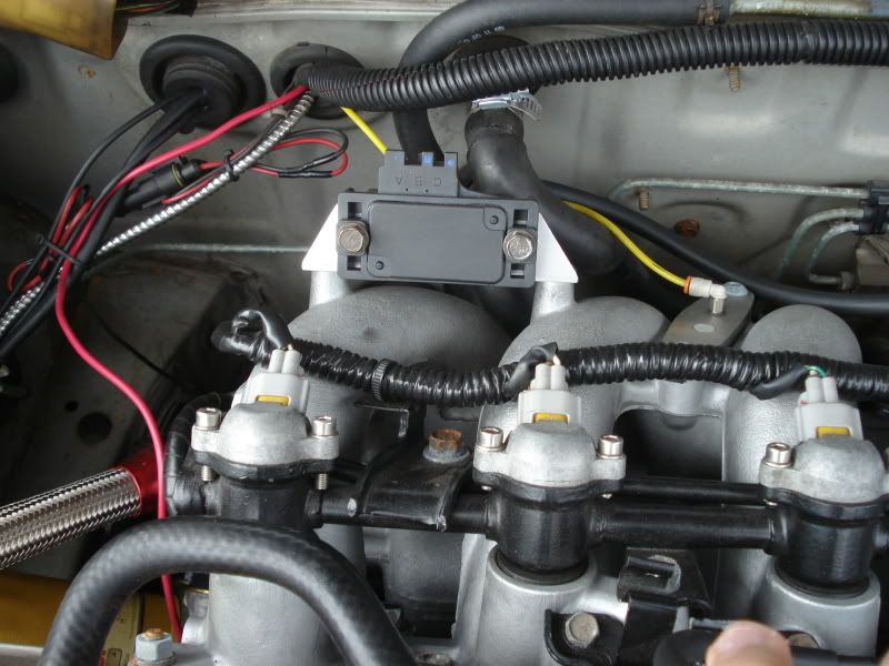
Step 1) Install MAP Sensor, I made a bracket to mount it to a convenient spot on the intake plenum. I teed off the boost signal from the manifold.

Step 2) Connectorize the MAP sensor... I used a FAST brand sensor that came with a connector. There are three wires, Ground, +5V supply, and 0 to 5V output.

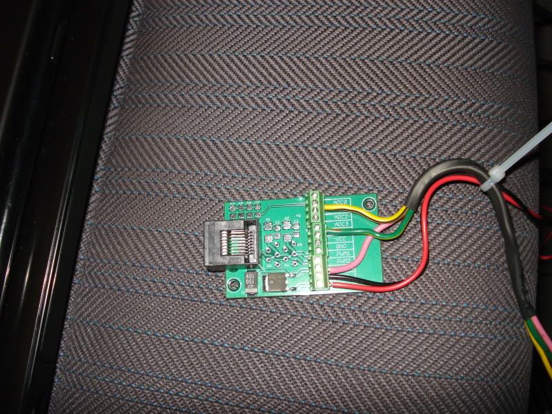
Step 3) Wire the breakout box. The terminals are labeled, so it’s pretty self-explanatory. The board has a voltage regulator that can supply 5 volts to sensors like the GM 3BAR (another great example of Nismotronic going the extra step) I hooked up the pressure signal into the ADC1 input. To utilize the 5V output line you will need to provide the breakout box with 12 volts.

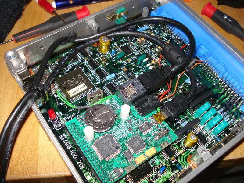
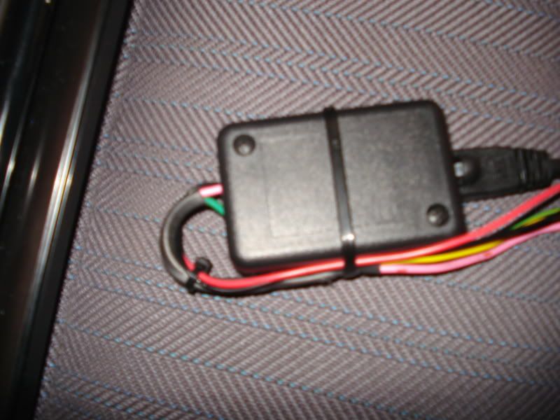
Sep 4) Hook up the RJ45 cable to the NEMU board and breakout box. I buttoned up the break out box and used a few zip ties to strain relief the wires.


Step 5) Input the calibration constants in the software. They can be found in the ADC inputs tab in the "Settings window"
enjoy
-dave
Step 1) Install MAP Sensor, I made a bracket to mount it to a convenient spot on the intake plenum. I teed off the boost signal from the manifold.

Step 2) Connectorize the MAP sensor... I used a FAST brand sensor that came with a connector. There are three wires, Ground, +5V supply, and 0 to 5V output.

Step 3) Wire the breakout box. The terminals are labeled, so it’s pretty self-explanatory. The board has a voltage regulator that can supply 5 volts to sensors like the GM 3BAR (another great example of Nismotronic going the extra step) I hooked up the pressure signal into the ADC1 input. To utilize the 5V output line you will need to provide the breakout box with 12 volts.

Sep 4) Hook up the RJ45 cable to the NEMU board and breakout box. I buttoned up the break out box and used a few zip ties to strain relief the wires.


Step 5) Input the calibration constants in the software. They can be found in the ADC inputs tab in the "Settings window"
enjoy
-dave


 Back to top
