This thread is to document how to install and use the ADC feature of the NEMU.
This feature allows you to log any 0-5 volt signal from a sensor. That includes wideband o2 sensors (AEM, PLX, Innovate, Zeitronix, etc), Oil Pressure sending units, EGT sensors and the list goes on and on!!
We will be providing a ADC Break-Out box with each order, so you can easily wire your ADC channels and some of the other future features (5 volt output, ground points, pwm outputs, etc) into the NEMU.
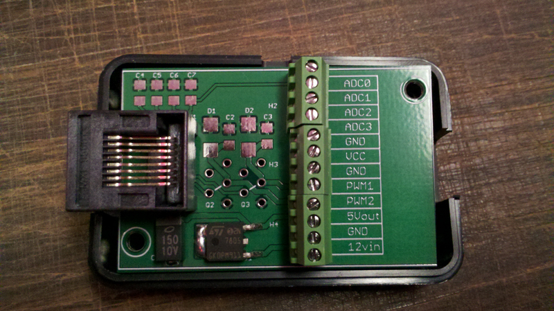
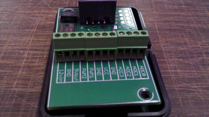
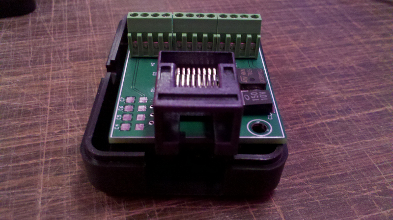
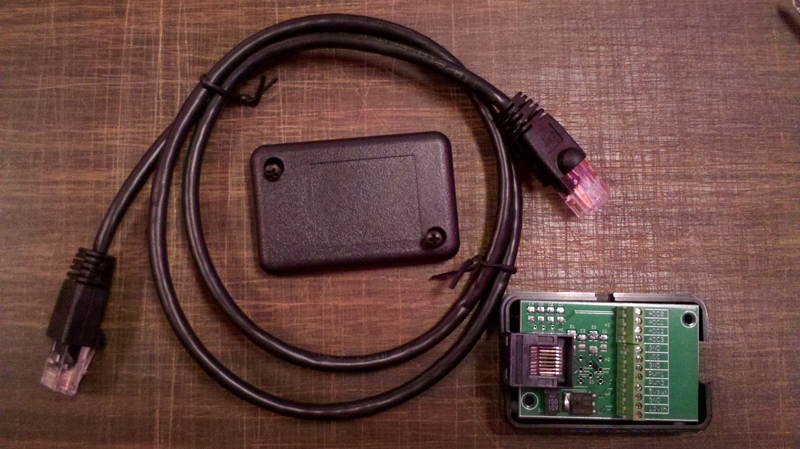
Here are a few pictures of the Break-Out box that we will be using.
You can see in the pictures that there is a RJ45 connector on one side and a screw terminal on the other. The screw terminal is labeled as to what the slot is intended to be used for.
ADC0-ADC3 are the channels that you would use for logging a wideband or any other 0-5 volt sensor through the NEMU.
Here is an example of how to run the wiring.
Strip off the shielding, it doesn't have to be very much and insert it into the slot which you want to the wideband or sensor to be logged through.
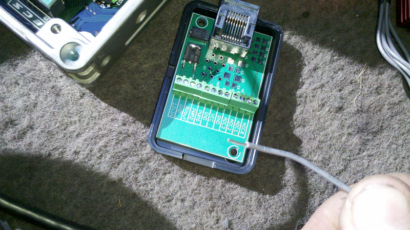
I chose ADC0, which correlates to ADC1 in the NismoTronic RT software.
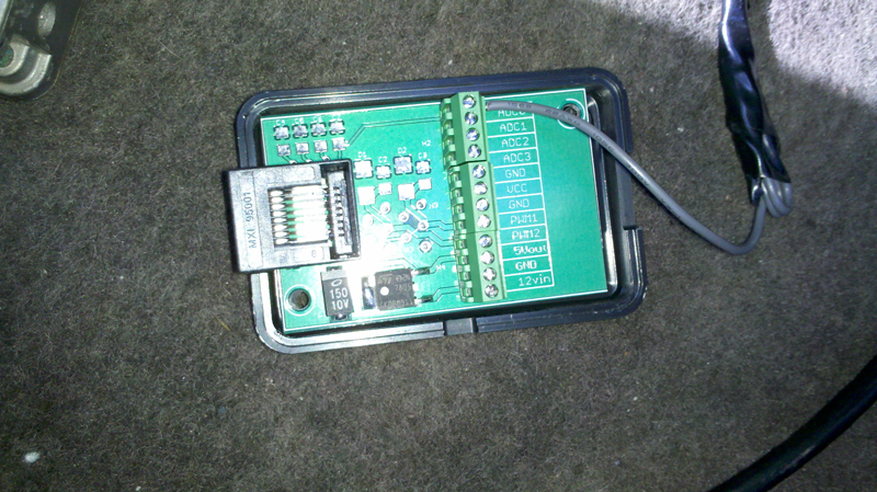
This is what it looks like all hooked up.. don't mind the mess.
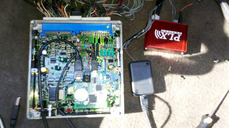
The breakout boxes RJ45 connects to the NEMU RJ45 connector with your basic cable. The PLX wideband then connects to the screw terminal side of the Break-Out box, completing the circuit.
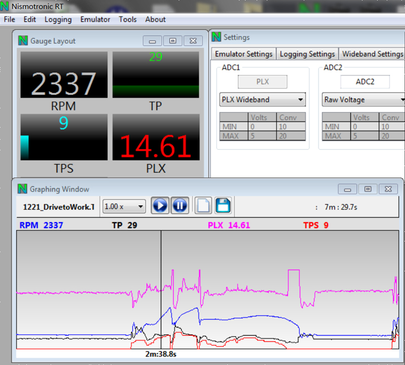
And here is the end result, with PLX selected as the sensor for ADC1 and you can see the AFR being displayed on the screen.
This feature allows you to log any 0-5 volt signal from a sensor. That includes wideband o2 sensors (AEM, PLX, Innovate, Zeitronix, etc), Oil Pressure sending units, EGT sensors and the list goes on and on!!
We will be providing a ADC Break-Out box with each order, so you can easily wire your ADC channels and some of the other future features (5 volt output, ground points, pwm outputs, etc) into the NEMU.
Here are a few pictures of the Break-Out box that we will be using.
You can see in the pictures that there is a RJ45 connector on one side and a screw terminal on the other. The screw terminal is labeled as to what the slot is intended to be used for.
ADC0-ADC3 are the channels that you would use for logging a wideband or any other 0-5 volt sensor through the NEMU.


Here is an example of how to run the wiring.
Strip off the shielding, it doesn't have to be very much and insert it into the slot which you want to the wideband or sensor to be logged through.

I chose ADC0, which correlates to ADC1 in the NismoTronic RT software.

This is what it looks like all hooked up.. don't mind the mess.
The breakout boxes RJ45 connects to the NEMU RJ45 connector with your basic cable. The PLX wideband then connects to the screw terminal side of the Break-Out box, completing the circuit.

And here is the end result, with PLX selected as the sensor for ADC1 and you can see the AFR being displayed on the screen.


 Back to top
