


Ok fellas, first off props go to @eggman for this idea WHICH YOU CAN ALSO REFERENCE HERE (who if I'm not mistaken got the idea from @Chriscar), but I took it a little further with what I did and decided to make a more detailed How To. This is going in my B14, but I might be do it in my B13 in the future and wanted to have this for referencing.
This was done with VDO Water and Oil Temp and Oil Psi gauges in a 42 Draft Designs 3 gauge single din face plate. (ignore that Scosche, antenna adapter bag, not related to this install)
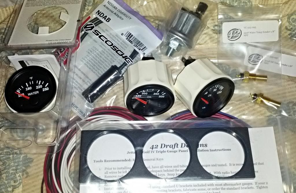
FIRST
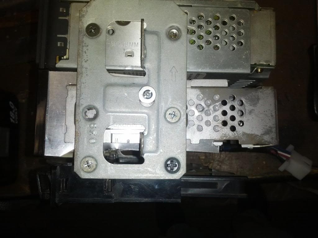
Find an old radio to take apart for the chassis. I used a tape player from an old Altima i found in the junk yard. Installed the gauges into the face plate and test fitted it to the chassis. It bows a little which we'll deal with later. You will be hot gluing it on but I didnt yet so it made connecting my wires easier.
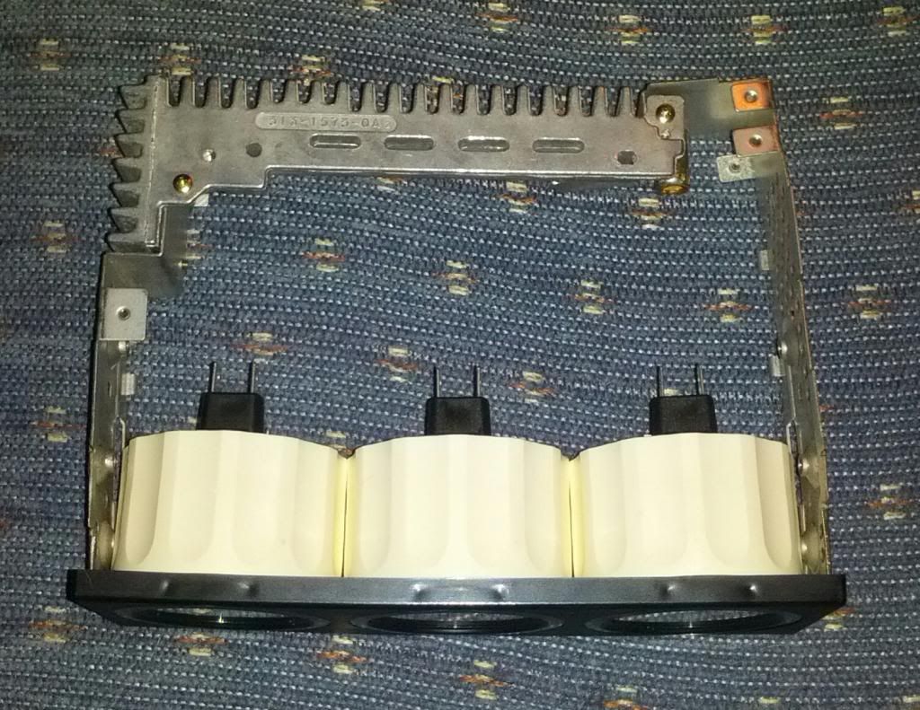
NEXT
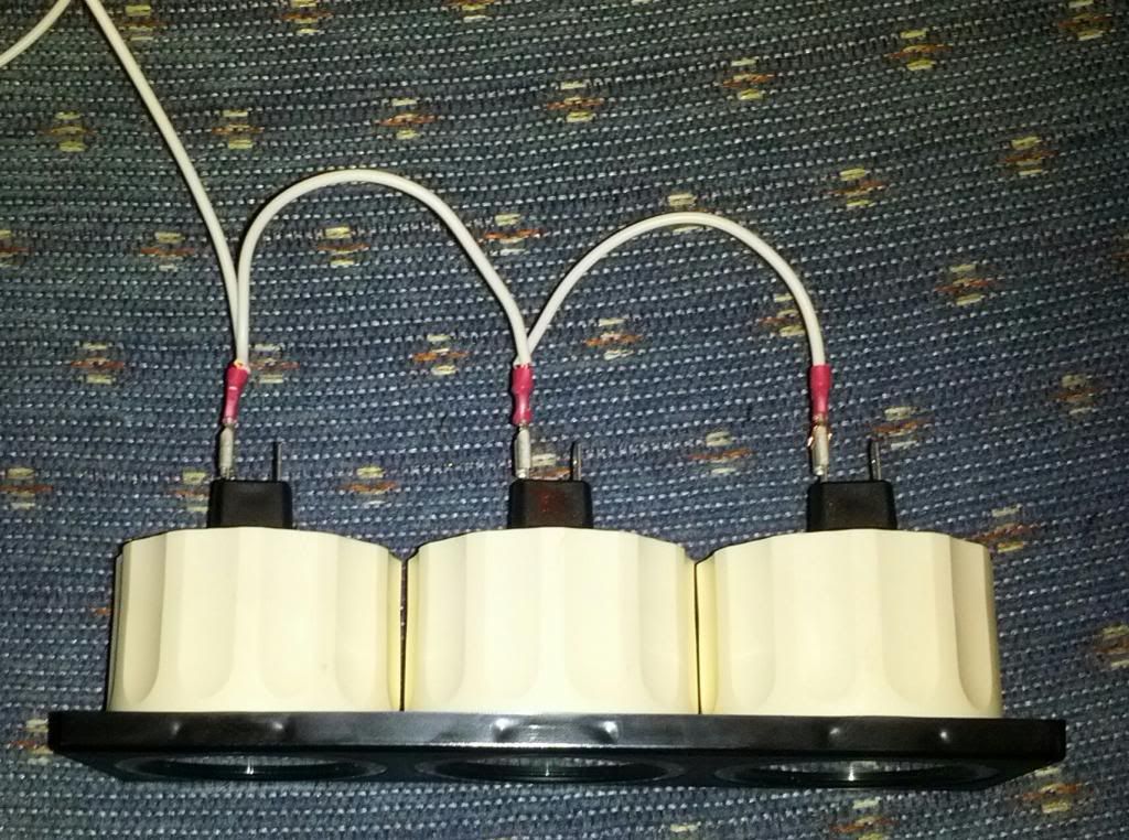
Start connecting your wires. Start at one side (i choose the right side to have my pigtail end up on the left) and work your way over with each wire. For color referencing (in my example) this is what I used in case anyone cares.
White = Bulb +
Black = Bulb - and Gauge -
Red = Gauge +
Blue = Water Temp Signal
Green = Oil Psi Signal
Light Blue = Oil Temp Signal
NEXT - Making Pigtail
Ok at this step you have 2 options.
Option 1 is what Jay choose to do, which I started to do but couldn't find a female to my male plug i was going to use. What you want to do is just go to the junk yard and cut a male, with matching female, pigtail with enough wires to connect yours to. Then obviously just connect with butt connectors and done.
Option 2 is what I ended up doing and a little more involved. I went to Radio Shack and for $6 got a Male and Female Molex 9 Pin Interlocking Connector.
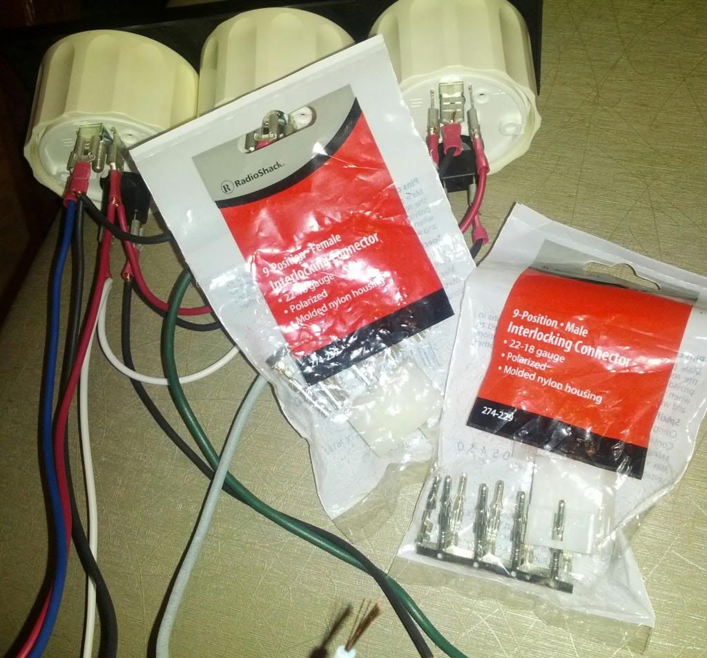
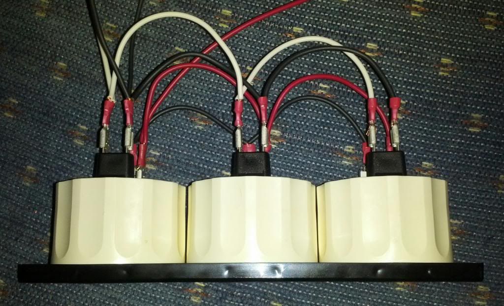
You crimp each wire to its own Pin, then insert it into the white plug housing, creating your own plug from scratch basically. Do this for both the male and female sides obviously, making sure to line up the same colors to each other.
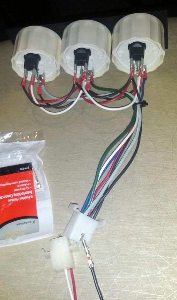
Your end product will give you something like this
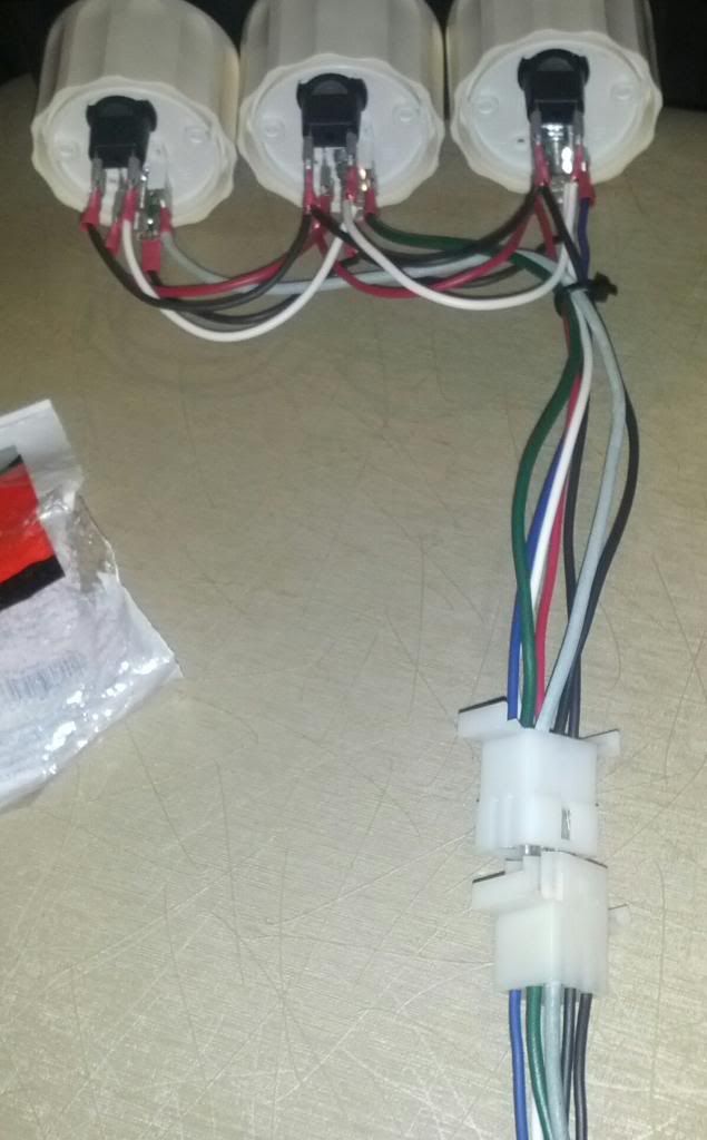
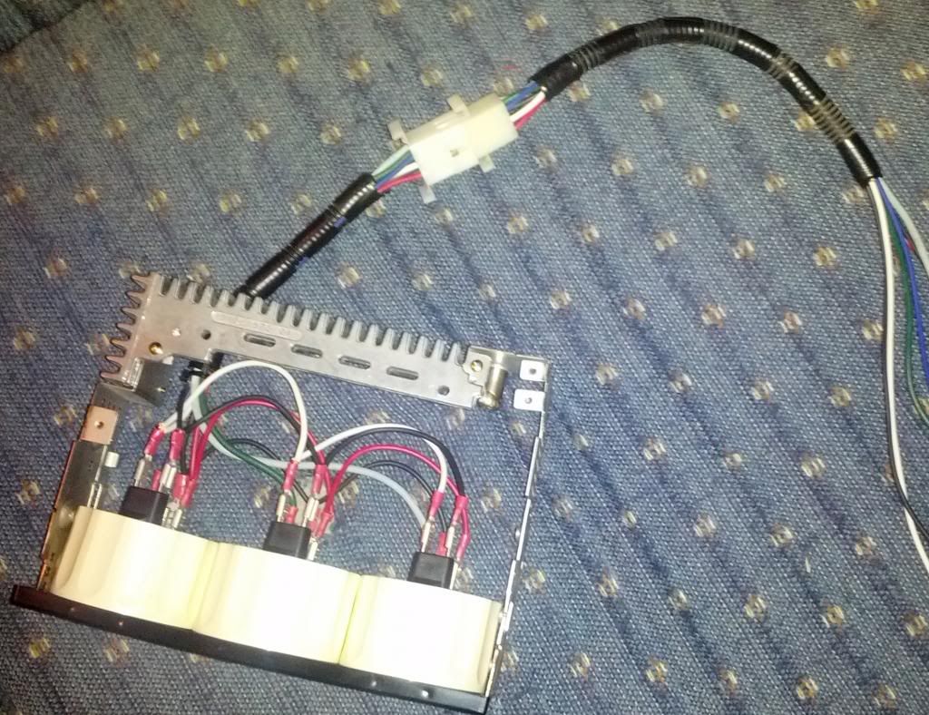
After all the wires are in, go ahead and throw a wire loom over the wires to make it look nice and clean.
IF YOU RUN INTO THE PROBLEM WITH THE FACEPLATE NOT SITTING FLUSH (will sit slightly recessed) HERE IS WHAT I DID TO REMEDY
Yes you will run into the issue that the gauges face plate will sit recessed if you use the radio as a frame. What I did was got some spare sheet metal (this was thin (.020 gauge) aluminum so something a little thicker might be better to the point you may not even need to use the radio frame but this was what i had at the time).
You cut the sheet metal to JUST fit nice and snug into the sides of the face plate. Then you line up the face plate right under the radio (using it to get your positioning) and slide the radio bracket over the sheet metal trimming the sheet metal as needed. Again if you use a thicker more sturdy metal you might not have to even use the radio frame, but I did for reinforcement. Once I had it where I wanted it to sit, I drilled a hole through the sheet metal where the back screw hole was and put the screw in. The sheet metal acts as an extender to the radio frame so the face plate will sit flush. NOTE: I grinded down the front 2 screw holes flush so that it sit up against the gauge more flush, not necessary, but doesnt hurt.
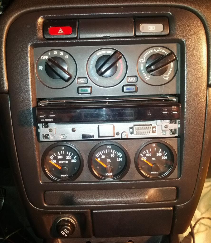
Here is my final result.
I grounded my wires to some of the screws around the center console.
Gauge lights were wired to the dimmer.
Power to the gauges I haven't yet connected as I want to find a nice "clean" one.
Wires for the sensor I ran up and out where the nozzles for the AC come out of the firewall as I dont have AC anymore so there's no hoses in the way. All these wires again were loomed for a cleaner look.
ON GOING PROJECT SO CHECK BACK FOR UPDATES OF THIS HOW TO, COMPLETING THE INSTALL. THIS INCLUDES FITTING IN THE DIN AND RUNNING WIRES TO SENSORS FROM THE FEMALE PLUG. IF YOU HAVE ANY QUESTION, LET ME KNOW!
CHAPTER 2: Water Temp Sensor
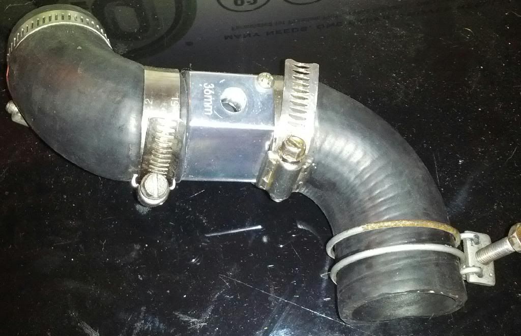
This one is pretty easy. First lets discuss the options. More people want to read the temps of the coolant as it exists the engine, which would be the upper rad hose. You can use the rad hose adapter in which you would cut your rad hose in half and have to run a ground wire from the adapter to the chassis. I actually originally did this, but I just wasnt feeling it and I didnt wana run the extra ugly ground wire off of it. Heres a picture.
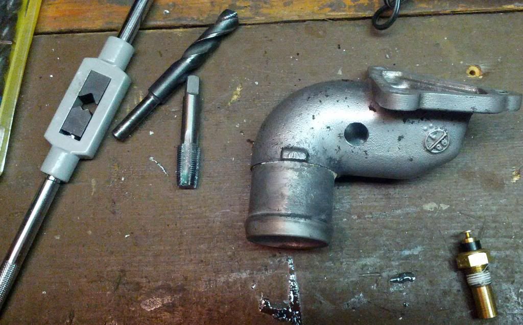
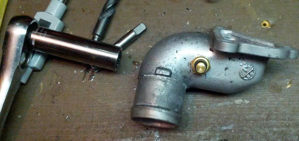
So what I did was drilled and tapped my water neck and fitted the sensor in. You wana be careful as the water neck is soft aluminum. IIRC the drill bit size for tapping 1/8 npt calls for 11/32, but I couldnt find one so I believe I used a 5/16th bit which made it slightly smaller than the sensors threading. I used a 1/8th npt tap in the kit from Harbor Freight but here is where I made a mistake. With my first water neck I threaded the tap all the way in. That ended up making the hole to big for the sensor. It threaded in the hole but felt loose. With my other back up water neck (i planned on making a mistake lol) I only use the tip of the tap. Just the tip to get it started then I basically threaded the rest of the hole by just tightening down the sensor. Felt MUCH better.
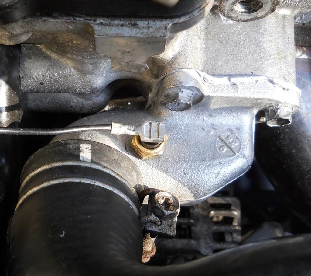
Throw a bead of rtv on her and reinstall. Here how it looks (Photo below courtesy Jay, I was so tired I forgot to snap a picture of mine installed)
CHAPTER 3: Oil Pressure Sensor
This will be installed via a NisSport Adapter on the back of the block where the Low Pressure warning light is connected.
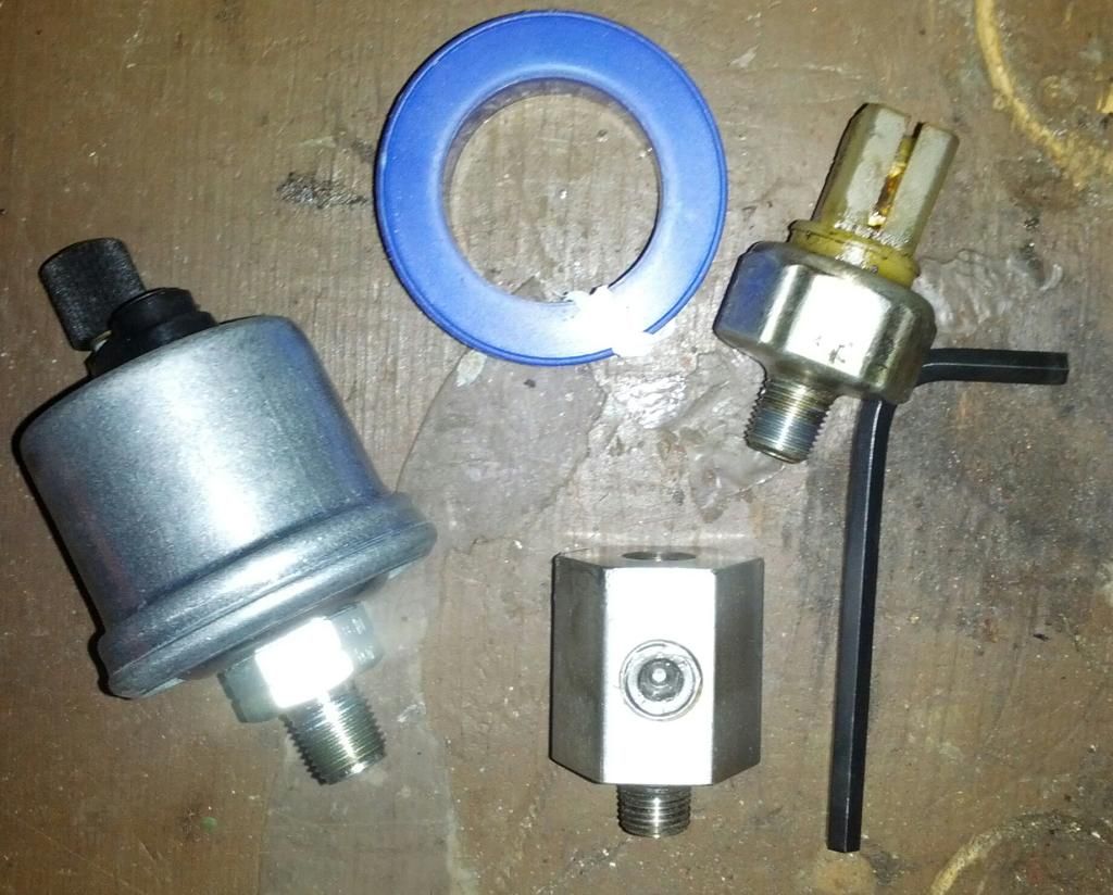
Here we go. Teflon tape, sensor, adapter. First obviously you want to plug the holes you arent going to be using. I put teflon tape on all plugs and tightened em down.
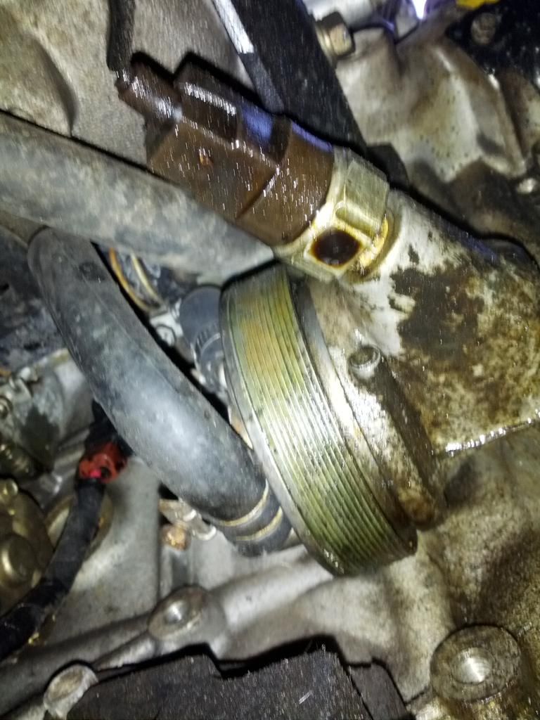
Locate the Low pressure sensor. Here is mine on the DET block. I also dont have power steering so accesses might be a little tighter for you. It should be somewhere above the pass CV axle. [Yeah I think maybe I need a new sensor as this one looks like it might have a slow drop lol].
Plug the back end of the adapter with the OE sensor, screw it in to where the open hole has enough free space around it to put in the pressure sensor.
I used teflon tape on everything I screwed in and get good readings, just dont over do it. TIP wrap it couter clock wise so you dont unwrap it when screwing it into place. Replug in the sensor. I ran a wire down from the firewall and connected it right to the pressure sensor.
DONE.
CHAPTER 4: Oil Temp Sensor
Ok, this has another two good options that I have done both keeping one for a back up. The first option which will be my back up is drill/tap the side of the oil pan for the sensor. This was my original idea and I got one that was already previously made, but the idea is pretty straight forward. But because my oil pan doesnt leak, I didnt want to worry about swapping the pans. The new idea I came up with that I will be trying first is drill/tap the drain plug for the sensor. I had 42Draft Designs make me one from an steel OE style plug. Hopefully enough of the sensor gets covered to get a good reading so we'll find out once I get it installed next oil change. It doesnt stick out lower than the actual pan so I find no issue with doing it this way.
******START HERE ABOVE IDEA DIDNT WORK OUT SEE BELOW******
SO becuz there isnt much meat left when you drill out the plug, there structural strength of it is CRAP. I went to tighten in the plug and barely got it tight at all and CRACK the threads split (you can see in the below picture). I'm going with the back up idea on the next oil change which includes dropping the low oil pan for this new one that has already been tapped as you can see.
This was done with VDO Water and Oil Temp and Oil Psi gauges in a 42 Draft Designs 3 gauge single din face plate. (ignore that Scosche, antenna adapter bag, not related to this install)
FIRST
Find an old radio to take apart for the chassis. I used a tape player from an old Altima i found in the junk yard. Installed the gauges into the face plate and test fitted it to the chassis. It bows a little which we'll deal with later. You will be hot gluing it on but I didnt yet so it made connecting my wires easier.
NEXT
Start connecting your wires. Start at one side (i choose the right side to have my pigtail end up on the left) and work your way over with each wire. For color referencing (in my example) this is what I used in case anyone cares.
White = Bulb +
Black = Bulb - and Gauge -
Red = Gauge +
Blue = Water Temp Signal
Green = Oil Psi Signal
Light Blue = Oil Temp Signal
NEXT - Making Pigtail
Ok at this step you have 2 options.
Option 1 is what Jay choose to do, which I started to do but couldn't find a female to my male plug i was going to use. What you want to do is just go to the junk yard and cut a male, with matching female, pigtail with enough wires to connect yours to. Then obviously just connect with butt connectors and done.
Option 2 is what I ended up doing and a little more involved. I went to Radio Shack and for $6 got a Male and Female Molex 9 Pin Interlocking Connector.
You crimp each wire to its own Pin, then insert it into the white plug housing, creating your own plug from scratch basically. Do this for both the male and female sides obviously, making sure to line up the same colors to each other.
Your end product will give you something like this
After all the wires are in, go ahead and throw a wire loom over the wires to make it look nice and clean.
IF YOU RUN INTO THE PROBLEM WITH THE FACEPLATE NOT SITTING FLUSH (will sit slightly recessed) HERE IS WHAT I DID TO REMEDY
Yes you will run into the issue that the gauges face plate will sit recessed if you use the radio as a frame. What I did was got some spare sheet metal (this was thin (.020 gauge) aluminum so something a little thicker might be better to the point you may not even need to use the radio frame but this was what i had at the time).
You cut the sheet metal to JUST fit nice and snug into the sides of the face plate. Then you line up the face plate right under the radio (using it to get your positioning) and slide the radio bracket over the sheet metal trimming the sheet metal as needed. Again if you use a thicker more sturdy metal you might not have to even use the radio frame, but I did for reinforcement. Once I had it where I wanted it to sit, I drilled a hole through the sheet metal where the back screw hole was and put the screw in. The sheet metal acts as an extender to the radio frame so the face plate will sit flush. NOTE: I grinded down the front 2 screw holes flush so that it sit up against the gauge more flush, not necessary, but doesnt hurt.
Here is my final result.
I grounded my wires to some of the screws around the center console.
Gauge lights were wired to the dimmer.
Power to the gauges I haven't yet connected as I want to find a nice "clean" one.
Wires for the sensor I ran up and out where the nozzles for the AC come out of the firewall as I dont have AC anymore so there's no hoses in the way. All these wires again were loomed for a cleaner look.
ON GOING PROJECT SO CHECK BACK FOR UPDATES OF THIS HOW TO, COMPLETING THE INSTALL. THIS INCLUDES FITTING IN THE DIN AND RUNNING WIRES TO SENSORS FROM THE FEMALE PLUG. IF YOU HAVE ANY QUESTION, LET ME KNOW!
CHAPTER 2: Water Temp Sensor
This one is pretty easy. First lets discuss the options. More people want to read the temps of the coolant as it exists the engine, which would be the upper rad hose. You can use the rad hose adapter in which you would cut your rad hose in half and have to run a ground wire from the adapter to the chassis. I actually originally did this, but I just wasnt feeling it and I didnt wana run the extra ugly ground wire off of it. Heres a picture.
So what I did was drilled and tapped my water neck and fitted the sensor in. You wana be careful as the water neck is soft aluminum. IIRC the drill bit size for tapping 1/8 npt calls for 11/32, but I couldnt find one so I believe I used a 5/16th bit which made it slightly smaller than the sensors threading. I used a 1/8th npt tap in the kit from Harbor Freight but here is where I made a mistake. With my first water neck I threaded the tap all the way in. That ended up making the hole to big for the sensor. It threaded in the hole but felt loose. With my other back up water neck (i planned on making a mistake lol) I only use the tip of the tap. Just the tip to get it started then I basically threaded the rest of the hole by just tightening down the sensor. Felt MUCH better.
Throw a bead of rtv on her and reinstall. Here how it looks (Photo below courtesy Jay, I was so tired I forgot to snap a picture of mine installed)
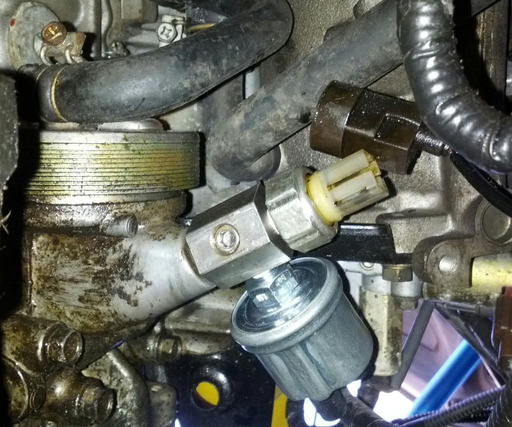
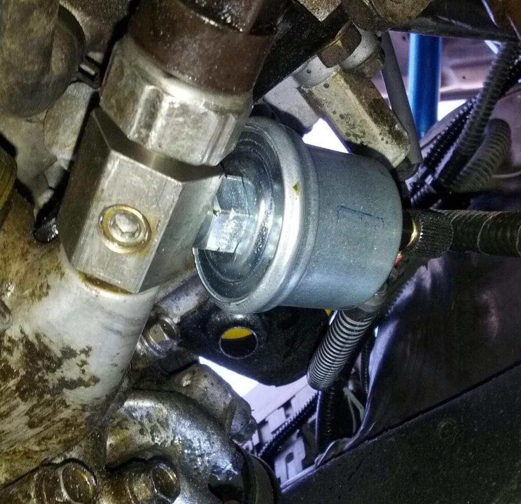
CHAPTER 3: Oil Pressure Sensor
This will be installed via a NisSport Adapter on the back of the block where the Low Pressure warning light is connected.
Here we go. Teflon tape, sensor, adapter. First obviously you want to plug the holes you arent going to be using. I put teflon tape on all plugs and tightened em down.
Locate the Low pressure sensor. Here is mine on the DET block. I also dont have power steering so accesses might be a little tighter for you. It should be somewhere above the pass CV axle. [Yeah I think maybe I need a new sensor as this one looks like it might have a slow drop lol].
Plug the back end of the adapter with the OE sensor, screw it in to where the open hole has enough free space around it to put in the pressure sensor.
I used teflon tape on everything I screwed in and get good readings, just dont over do it. TIP wrap it couter clock wise so you dont unwrap it when screwing it into place. Replug in the sensor. I ran a wire down from the firewall and connected it right to the pressure sensor.
DONE.
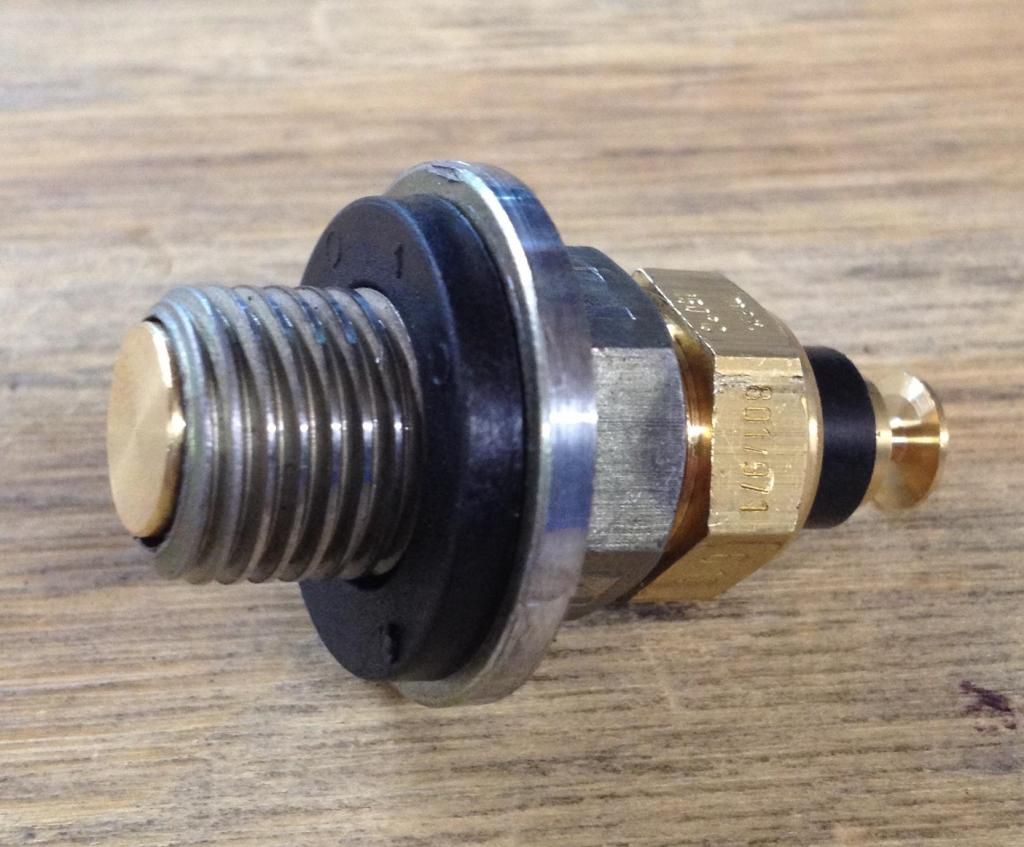
CHAPTER 4: Oil Temp Sensor
Ok, this has another two good options that I have done both keeping one for a back up. The first option which will be my back up is drill/tap the side of the oil pan for the sensor. This was my original idea and I got one that was already previously made, but the idea is pretty straight forward. But because my oil pan doesnt leak, I didnt want to worry about swapping the pans. The new idea I came up with that I will be trying first is drill/tap the drain plug for the sensor. I had 42Draft Designs make me one from an steel OE style plug. Hopefully enough of the sensor gets covered to get a good reading so we'll find out once I get it installed next oil change. It doesnt stick out lower than the actual pan so I find no issue with doing it this way.
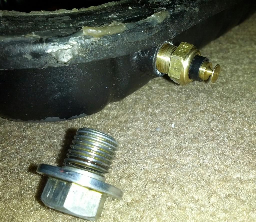
******START HERE ABOVE IDEA DIDNT WORK OUT SEE BELOW******
SO becuz there isnt much meat left when you drill out the plug, there structural strength of it is CRAP. I went to tighten in the plug and barely got it tight at all and CRACK the threads split (you can see in the below picture). I'm going with the back up idea on the next oil change which includes dropping the low oil pan for this new one that has already been tapped as you can see.
Last edited by speedricer
on 2014-10-20
at 03-57-03.


") !!
!!


")


