


Before I Begin I Want To Thank Few Members Who Had Done Previous How To's . SinisterSentra91 & M0J0 .
First Started Off Using The Diagrams That SinisterSentra91 Posted .
Here's The Link For More Info On His Thread (http://www.sr20-forum.com/audio-electronics/38323-digital-gauge-cluster-info.html)
But I Wanted To Know What The Wires Were .
So M0J0 Posted What The Center Plug Was On The NX1600 Digital Cluster.
This Is What He Posted For The Center Plug(Black 12 Pin Plug)
The Pinout Of That Plug Is As Follows:
1...7
2...8
3...9
4...10
5...11
6...12
1 - Speed sensor positive (but doesn't really matter)
2 - Illumination (not sure whether positive or negative)
3 - Speed sensor negative (but doesn't really matter)
4 - Illumination clock
5 - Tachometer
6 - Illumination (not sure whether positive or negative)
7 - Ignition
8 - Temperature
9 - Fuel level
10 - Ground
11 - Speed signal to ECU
12 - Battery for clock (so the cluster can "remember" the time)
This To Me Was My Foot In The Door To Begin My Wiring Process .
Than After A Few More Post I Bumped Into This Diagram Which Is The Prefect Solution For The Labeling Process .
Now Using This Diagram :
Posted By Toolapcfan
Here's The Link For More Info On His Thread (HOW TO: B13 cable/electronic cluster swaps - SR20 Forum)
93-'94 Electronic speedometer cluster wiring info:

M30 Plugs in horizontally behind the temp gauge on the bottom left hand side of the cluster (when looking at the back)
M32 Plugs in horizontally behind the fuel gauge on the bottom right hand side of the cluster (when looking at the back)
M33 Plugs in horizontally behind the tach
M102 Plugs in vertically above M32
M102 - 7 wires
1 G/L Fuel gauge
2 R/W Door open indicator
3 B Ground for water temp, fuel, tach and speedometer gauges as well as airbag indicator and clock
5 R/B Fuel indicator
6 Y/G Speedometer gauge
7 L/R ABS indicator
8 G/B Left hand turn signal indicator
M32 - 9 wires
9 Y Seatbelt indicator
10 L/W Washer indicator (Canada only)
11 R/B High beam on indicator
12 B Ground for high beam on indicator
13 R/W Airbag indicator
14 Y/G(4door and NX)Y/B(2door) Seatbelt indicator
15 Y Power for Abs, fuel, brake, overdrive off(auto), door, malfunction, washer(Canada), charge, and oil indicator lights, water temp, fuel, tach, and speedo gauges.
16 G Speedometer gauge
18 R Speedometer gauge
M33 - 5 wires
19 B/Y Overdrive off indicator (auto only)
21 R/L Meter illumination
25 G/Y(2door)G/R(4door and NX) Cruise on indicator
26 G/Y Right hand turn signal indicator
27 B Ground for turn signal indicators
M30 - 10 wires
31 PU Brake indicator
32 Y/B Brake indicator
33 Y/G Oil indicator
35 OR/B Malfunction indicator
36 Y/R Charge indicator
37 R/B Clock
38 L Clock illumination
39 L/B Tachometer
40 R/Y Meter illumination
41Y/G Water temp gauge
Another Diagram For The 91-92 B13 Se-r Owners
Posted By eurokid21

Edit On The Diagram Pin 34 Is Brake
Once I Had All This Info It Became Way More Clearer & Simpler To Me .
So I Made This Diagram Using My NX Cluster & The Center Plug M0J0 Posted .(Using The 93-94 Se-R Diagram)
Now I Begun My Process In Getting This Wiring Completed .
After Using Both The 93-94 Se-r Diagram & The NX Diagram Labelled Where My Wires Had To Go .
I Also Noticed While Labeling That Some Of The Illuminations Are Labeled With R/Y or R/B
When I Did The Labellings , My Illuminations Were The Last I Did Since I Had (2) Red/Yellow & (2) Red/Blue I Just Grouped Them By Color
There Are (3) Ignitions (Yellow Wires) I Grouped Them Also
This Was My Final For The Wiring Process
NX Wiring -------------------------------------------------------------------- 93-94 Se-R
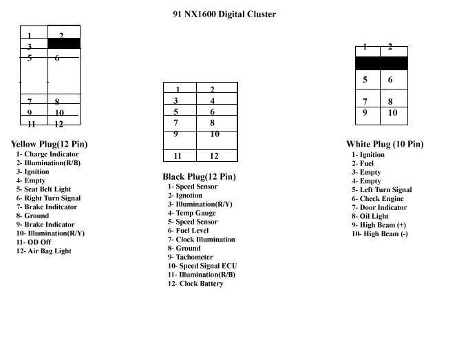
Yellow Plug (12 Pins)
Pin #1 ------------------------------------------------------------------------Plug M30 (Pin 36)
Pin #2 ------------------------------------------------------------------------Plug M33 (Pin 21)
Pin #3 ------------------------------------------------------------------------Plug M32 (Pin 15)
Pin #4 ------------------------------------------------------------------------ EMPTY
Pin #5 ------------------------------------------------------------------------Plug M32 (Pin 9)
Pin #6 ------------------------------------------------------------------------Plug M33 (Pin 26)
Pin #7 ------------------------------------------------------------------------Plug M30 (Pin 32)
Pin #8 ------------------------------------------------------------------------Plug M33 (Pin 27)
Pin #9 ------------------------------------------------------------------------Plug M30 (Pin 31)
Pin #10 -----------------------------------------------------------------------Plug M30 (Pin 40)
Pin #11 -----------------------------------------------------------------------Plug M33 (Pin 19)
Pin #12 -----------------------------------------------------------------------Plug M32 (Pin 13)
Black Center Plug (12 Pins)
Pin #1 ------------------------------------------------------------------------Plug M32 (Pin 16)
Pin #2 ------------------------------------------------------------------------Plug M32 (Pin 15)
Pin #3 ------------------------------------------------------------------------Plug M30 (Pin 40)
Pin #4 ------------------------------------------------------------------------Plug M30 (Pin 41)
Pin #5 ------------------------------------------------------------------------Plug M32 (Pin 18)
Pin #6 ------------------------------------------------------------------------Plug M102 (Pin 1)
Pin #7 ------------------------------------------------------------------------Plug M30 (Pin 38)
Pin #8 ------------------------------------------------------------------------Plug M102 (Pin 3)
Pin #9 ------------------------------------------------------------------------Plug M30 (Pin 39)
Pin #10 -----------------------------------------------------------------------Plug M102 (Pin 6)
Pin #11 -----------------------------------------------------------------------Plug M32 (Pin 21)
Pin #12 -----------------------------------------------------------------------Plug M30 (Pin 37)
White Plug (10 Pins)
Pin #1 ------------------------------------------------------------------------Plug M32 (Pin 15)
Pin #2 ------------------------------------------------------------------------Plug M102 (Pin 5)
Pin #3 ------------------------------------------------------------------------ EMPTY
Pin #4 ------------------------------------------------------------------------ EMPTY
Pin #5 ------------------------------------------------------------------------Plug M102 (Pin 8)
Pin #6 ------------------------------------------------------------------------Plug M30 (Pin 35)
Pin #7 ------------------------------------------------------------------------Plug M102 (Pin 2)
Pin #8 ------------------------------------------------------------------------Plug M30 (Pin 33)
Pin #9 ------------------------------------------------------------------------Plug M32 (Pin 11)
Pin #10 -----------------------------------------------------------------------Plug M32 (Pin 12)
I Hope This Was Alittle More Helpful & More Understanding Where Everyone Can Do & Enjoy A New Modification On Their B13's
First Started Off Using The Diagrams That SinisterSentra91 Posted .
Here's The Link For More Info On His Thread (http://www.sr20-forum.com/audio-electronics/38323-digital-gauge-cluster-info.html)
But I Wanted To Know What The Wires Were .
So M0J0 Posted What The Center Plug Was On The NX1600 Digital Cluster.
This Is What He Posted For The Center Plug(Black 12 Pin Plug)
The Pinout Of That Plug Is As Follows:
1...7
2...8
3...9
4...10
5...11
6...12
1 - Speed sensor positive (but doesn't really matter)
2 - Illumination (not sure whether positive or negative)
3 - Speed sensor negative (but doesn't really matter)
4 - Illumination clock
5 - Tachometer
6 - Illumination (not sure whether positive or negative)
7 - Ignition
8 - Temperature
9 - Fuel level
10 - Ground
11 - Speed signal to ECU
12 - Battery for clock (so the cluster can "remember" the time)
This To Me Was My Foot In The Door To Begin My Wiring Process .
Than After A Few More Post I Bumped Into This Diagram Which Is The Prefect Solution For The Labeling Process .
Now Using This Diagram :
Posted By Toolapcfan
Here's The Link For More Info On His Thread (HOW TO: B13 cable/electronic cluster swaps - SR20 Forum)
93-'94 Electronic speedometer cluster wiring info:
M30 Plugs in horizontally behind the temp gauge on the bottom left hand side of the cluster (when looking at the back)
M32 Plugs in horizontally behind the fuel gauge on the bottom right hand side of the cluster (when looking at the back)
M33 Plugs in horizontally behind the tach
M102 Plugs in vertically above M32
M102 - 7 wires
1 G/L Fuel gauge
2 R/W Door open indicator
3 B Ground for water temp, fuel, tach and speedometer gauges as well as airbag indicator and clock
5 R/B Fuel indicator
6 Y/G Speedometer gauge
7 L/R ABS indicator
8 G/B Left hand turn signal indicator
M32 - 9 wires
9 Y Seatbelt indicator
10 L/W Washer indicator (Canada only)
11 R/B High beam on indicator
12 B Ground for high beam on indicator
13 R/W Airbag indicator
14 Y/G(4door and NX)Y/B(2door) Seatbelt indicator
15 Y Power for Abs, fuel, brake, overdrive off(auto), door, malfunction, washer(Canada), charge, and oil indicator lights, water temp, fuel, tach, and speedo gauges.
16 G Speedometer gauge
18 R Speedometer gauge
M33 - 5 wires
19 B/Y Overdrive off indicator (auto only)
21 R/L Meter illumination
25 G/Y(2door)G/R(4door and NX) Cruise on indicator
26 G/Y Right hand turn signal indicator
27 B Ground for turn signal indicators
M30 - 10 wires
31 PU Brake indicator
32 Y/B Brake indicator
33 Y/G Oil indicator
35 OR/B Malfunction indicator
36 Y/R Charge indicator
37 R/B Clock
38 L Clock illumination
39 L/B Tachometer
40 R/Y Meter illumination
41Y/G Water temp gauge
Another Diagram For The 91-92 B13 Se-r Owners
Posted By eurokid21
Edit On The Diagram Pin 34 Is Brake
Once I Had All This Info It Became Way More Clearer & Simpler To Me .
So I Made This Diagram Using My NX Cluster & The Center Plug M0J0 Posted .(Using The 93-94 Se-R Diagram)
Now I Begun My Process In Getting This Wiring Completed .
After Using Both The 93-94 Se-r Diagram & The NX Diagram Labelled Where My Wires Had To Go .
I Also Noticed While Labeling That Some Of The Illuminations Are Labeled With R/Y or R/B
When I Did The Labellings , My Illuminations Were The Last I Did Since I Had (2) Red/Yellow & (2) Red/Blue I Just Grouped Them By Color
There Are (3) Ignitions (Yellow Wires) I Grouped Them Also
This Was My Final For The Wiring Process
NX Wiring -------------------------------------------------------------------- 93-94 Se-R
Yellow Plug (12 Pins)
Pin #1 ------------------------------------------------------------------------Plug M30 (Pin 36)
Pin #2 ------------------------------------------------------------------------Plug M33 (Pin 21)
Pin #3 ------------------------------------------------------------------------Plug M32 (Pin 15)
Pin #4 ------------------------------------------------------------------------ EMPTY
Pin #5 ------------------------------------------------------------------------Plug M32 (Pin 9)
Pin #6 ------------------------------------------------------------------------Plug M33 (Pin 26)
Pin #7 ------------------------------------------------------------------------Plug M30 (Pin 32)
Pin #8 ------------------------------------------------------------------------Plug M33 (Pin 27)
Pin #9 ------------------------------------------------------------------------Plug M30 (Pin 31)
Pin #10 -----------------------------------------------------------------------Plug M30 (Pin 40)
Pin #11 -----------------------------------------------------------------------Plug M33 (Pin 19)
Pin #12 -----------------------------------------------------------------------Plug M32 (Pin 13)
Black Center Plug (12 Pins)
Pin #1 ------------------------------------------------------------------------Plug M32 (Pin 16)
Pin #2 ------------------------------------------------------------------------Plug M32 (Pin 15)
Pin #3 ------------------------------------------------------------------------Plug M30 (Pin 40)
Pin #4 ------------------------------------------------------------------------Plug M30 (Pin 41)
Pin #5 ------------------------------------------------------------------------Plug M32 (Pin 18)
Pin #6 ------------------------------------------------------------------------Plug M102 (Pin 1)
Pin #7 ------------------------------------------------------------------------Plug M30 (Pin 38)
Pin #8 ------------------------------------------------------------------------Plug M102 (Pin 3)
Pin #9 ------------------------------------------------------------------------Plug M30 (Pin 39)
Pin #10 -----------------------------------------------------------------------Plug M102 (Pin 6)
Pin #11 -----------------------------------------------------------------------Plug M32 (Pin 21)
Pin #12 -----------------------------------------------------------------------Plug M30 (Pin 37)
White Plug (10 Pins)
Pin #1 ------------------------------------------------------------------------Plug M32 (Pin 15)
Pin #2 ------------------------------------------------------------------------Plug M102 (Pin 5)
Pin #3 ------------------------------------------------------------------------ EMPTY
Pin #4 ------------------------------------------------------------------------ EMPTY
Pin #5 ------------------------------------------------------------------------Plug M102 (Pin 8)
Pin #6 ------------------------------------------------------------------------Plug M30 (Pin 35)
Pin #7 ------------------------------------------------------------------------Plug M102 (Pin 2)
Pin #8 ------------------------------------------------------------------------Plug M30 (Pin 33)
Pin #9 ------------------------------------------------------------------------Plug M32 (Pin 11)
Pin #10 -----------------------------------------------------------------------Plug M32 (Pin 12)
I Hope This Was Alittle More Helpful & More Understanding Where Everyone Can Do & Enjoy A New Modification On Their B13's
 Be the first to like this post.


