Very nice, thank you for reading and taking the time to address these points to narrow down the ideas.

Originally Posted by
BenFenner 
1) Breather filter on valve cover is not "acceptable" in turbo applications
This argument basically boils down to semantics. Call it acceptable or not, whatever... People can make up their own mind once they've read the information in these threads. There is a reason this method is considered unacceptable on N/A engines but acceptable on turbo engines. It is trivial to "do it right" on the N/A engine, so this method is silly. However on a turbo engine you have to balance coating the intercooler with oil versus not, making this method a somewhat viable option for turbo folks.
#1 Semantics, personal preference. Yes people without any testing or data will have a personal preference on this matter. Some feel that having near atmospheric pressure in their crankcase during boost is "fine". Others, who
have done the testing, who
KNOW that it is NOT fine, spend a thousand dollars on a belt driven vacuum pump and build their engines accordingly to improve power output and engine efficiency during boost. Clearly, if a breather on the valvecover was just "fine" for all applications, then nobody would be spending thousands of dollars on vacuum pumps. Furthermore, the factory would not have the WOT PCV tube if it was "fine" to leave a breather on the valvecover! SO far, ALL the OEM and high dollar applications ALL
use PCV during boost as a necessity. Only low dollar enthusiast projects, without data/testing, are the ones running breathers.
2) The breather filter on the valve cover does not maintain the stock prevention of pressurization of the crank case.
Like hell it doesn't. I think you're putting more meaning into this than there really is. Without splitting hairs, part of what the stock setup tries to prevent is the crankcase pressure from going over atmospheric. The stock setup lets pressure in the crank case over atmospheric enter the intake stream, limiting pressure in the crank case to atmospheric (or a tiny bit below). Putting a breather filter on the valve cover also limits pressure in the crank case to atmospheric as the pressure can vent to the atmosphere. That is all I mean by that component. You won't get 15 psi built up in the crank case, blowing out seals and wreaking all sorts of havoc. That's all.
Notice in that description that I spell out this method will NOT help promote ring seal and prevent blow-by (won't put a vacuum in the crank case, even the slightest amount). I also spell out that it will not help evacuate the crank case, again, because it doesn't put even the slightest vacuum to it.
But does it still prevent pressure build-up in the crank case? (Compare to someone sealing up the crankcase by capping every port off.) Yes, yes it does.
If the pressure is exiting the valvecover TO the atosphere during boost, then
THERE MUST BE HIGHER PRESSURE IN THE CRANK CASE. Air molecules would not flow OUT of the valvecover during boost if there was NO pressurization of the crank case. True that pressure does not RISE enough to blow out seals. And YES You nailed it- it will not help prevent ring seal and prevent blow-by. ALL true and your line of thinking is pristine. However, the fact is, you STILL have a slight pressurization of the crank case, any way you slice it. Therefore, the breather filter, does NOT prevent pressurization of the crank case, by definition.
3) Shorter hoses and/or an overall less restrictive system is better.
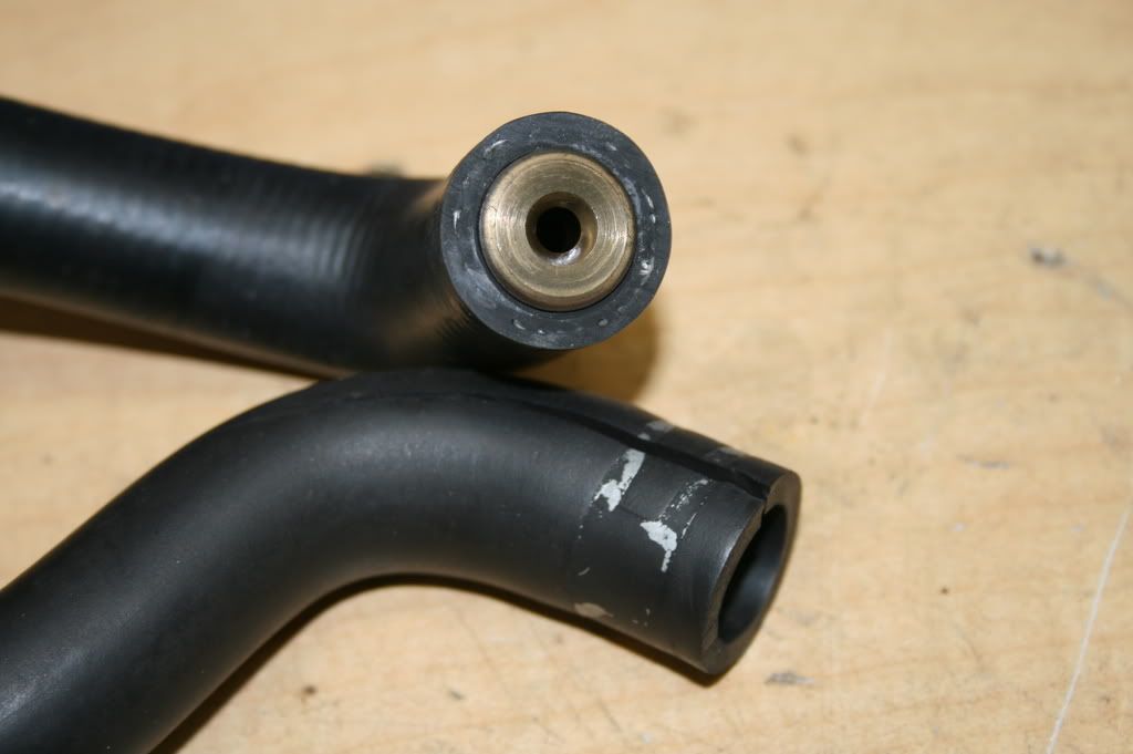
Sure, that's true. But I don't think 2 feet of hose versus 5 feet of hose is anything to worry about. Really, I just don't. The size of the hose on our stock setups is HUGE for the amount of air it needs to flow. Not only that, but there is a ~2.5mm restrictor in the line that makes the size of the hose almost irrelevant. As long as you keep the stock diameter hose throughout, you're going to be fine even with 10+ feet of it. This is a none issue IMO.
We need to do some testing, we cant just "think" something is better or worse. You started with TRUE because it is true, and then you "think" it isnt anything to worry about. You might be right, but true is true.
Also, I was actually not aware of any restrictor in the line. Have you seen this restrictor? Now I am madly curious.
4) Install the bung to the intake pipe at an angle to aid scavenging.
Of course. This is great advice, and I could have sworn I mentioned it somewhere in the text. I didn't put it in the images because it was too difficult to fit everything in. When I do my setup, I wil put the bung 45 degrees facing away from the direction of flow to aid scavenging. If I didn't specifically mention this as a really good idea, it was probably because I said this is going to be a primer and everything under the sun can't be spelled out here. I just didn't want to get into it I guess?
A minor detail, but one often overlooked is all. I am just trying to help you finish off the thread once and for all with every minute detail. You appreciate me adding attention to detail to all your hard work right? I hope so, that is why I am taking the time to do this.
5) Stop calling them "catch cans".
I understand you're not directing this at me, since I pretty much universally call them oil separators... But here's the thing. There are such things as catch cans. They do catch oil, and they do need to be drained. I've seen them work and fill and be drained with my own eyes. There are self draining oil seperators (like the factory unit) which shouldn't be called catch cans, but I don't call them catch cans, so...
Certainly NOT directly towards you. Only that people are constantly confused by the word "catch can". They see the black box on the redtop and call it a catch can when it is clearly not catching anything. I correct them, pointing out that it does not catch anything, and then 5 minutes later somebody else is calling it a catch can again. I think noobs to the PCV need to see that black can on the redtop as an "oil separator" not a catch can. And all your diagrams have the word "catch can" on them.
6) The PCV system provides a vacuum at all running conditions.
That would be ideal, however almost all factory setups fail to reach this goal. In turbo setups, they traditionally do their best at WOT to put a vacuum in the crankcase but they typically fail to do so. The best they can usually do is keep pressure down to a very minimum above atmospheric.
that WOULD be ideal, and the closer to ideal we get, the better. Shorter hoses, proper angles. vacuum pumps. good oil seals. high quality piston rings and proper break in procedure. testing and data. All of it counts.
And again, that restrictor. My redtop doesnt have one. Ive never seen one. Are you sure it exists? You know my memory is a little foggy- I seem to recall something there now that you mentioned it. But no, my redtop doesnt have a restrictor I looked and looked.
you mean this?
http://www.supercars.net/gallery/132464/1737/946320.jpg
Not all of them look like that. Some are just a nice open tube. Mine is. I think Nissan revised it at some point.


 Be the first to like this post.

