If you're reading this you've likely asked a question about crank case ventilation, catch can placement, correct PCV hose routing, or similar.
Grab yourself a beverage of your choice, sit back and relax. Keep reading to have all of your questions answered. If you came here looking for info on forced induction setups, read this N/A guide first then move on to https://www.sr20-forum.com/information-library/!42637-crank-case-ventilation-fully-explained-turbocharged-edition.html.
To understand what you're doing when you modify or repair the factory crank case ventilation system you should know how the factory systems works first before diving into modifying it or fixing it. It might also be nice to understand the history and evolution of the crank case ventilation system, so I'm going to start with the early SR20DE system and work up from there.
I know people like images so I won't hold off any longer.
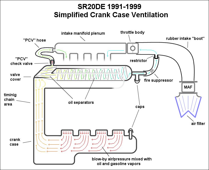
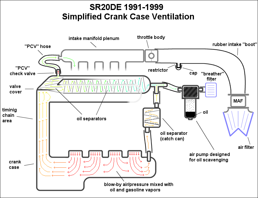
Here's the factory system:
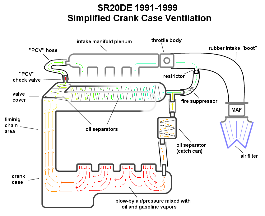
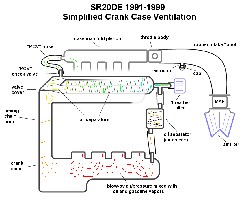
Now let me explain what's happening here. The piston rings don't seal perfectly, so there is some air that gets by them and we call that blow-by. This blow-by air is pressurized and will cause oil seals to fail and eventually will cause other major problems so it needs to be dealt with. Having a vacuum in the crank case is very good as it promotes ring seal and keeps windage losses (drag on the rotating crank caused by a cloud of oil in the crank case) to a minimum. Since having a vacuum in the crank case is good and having pressure there is bad, we must get rid of the pressure somehow.
The air comes in contact with a lot of oil in the crank case and basically turns into a mix of air and oil (along with a little bit of gasoline and water). This air/oil mix is represented by the red arrows in the crank case and as oil gets removed throughout the system I've made the color shift towards blue. I even showed little oil droplets condensing out of the air as it goes up through the "catch can" oil separator. I didn't show them everywhere in all the baffles, but you can imagine the same thing happening everywhere you see baffles.
The amount of air and oil can be quite significant, so Nissan put in two important pathways for the pressure to escape from the crank case because at times there can be a lot of air to evacuate.
On the left the air and oil can escape the crank case up along the timing chain portion of the block and into the valve cover. This is the usual pathway for the air to take.
On the right the oily air can escape the crank case (in times where there is excessive pressure to evacuate) through the provision in the side of the block, up through the oil separator (catch can) leaving the crank case.
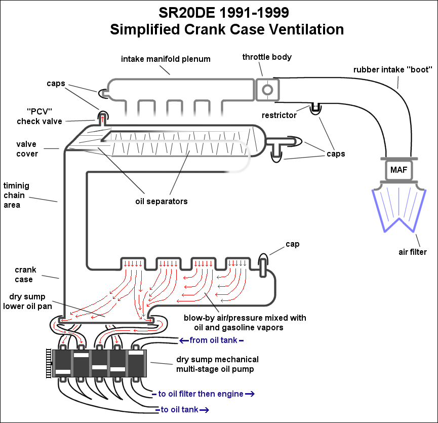
So the goal is to have a vacuum in the crank case, and this is accomplished on some vehicles with a dry sump oil system, but on regular vehicles the intake manifold is used for the source of vacuum. Basically the engine is setup to consume it's own blow-by gasses. Not a super great idea because it coats the intake in oil residue and lowers the effective octane of your fuel, but it certainly is efficient, practical, and good for the environment.
How does blow-by lower your octane? Blow-by gasses with any amount of oil in them will lower the effective octane rating of your fuel because the vaporized oil will ignite at lower energy levels than 87 octane (R+M/2) gasoline. The more of it you allow to enter the cylinder, the more you will have to worry about detonation. This is usually not a big worry for naturally aspirated engines, but obviously forced induction is a different story.
All right if you've been paying attention we now have the blow-by gasses up and out of the crank case and in the valve cover now. The gasses are going to continue on through the small PCV (positive crank-case ventilation) port at the top-left corner of the valve cover which includes a one-way check valve so things can only flow out (and not in). The gasses flow out of the PCV port and into the intake manifold where they are sucked back into the engine to get consumed and pushed out of the exhaust. Simple enough.
Now the gasses have a bit of oil mixed in with it, so on it's way out of the valve cover it passes through a labyrinth of baffles designed to help condense the oil and collect the oil from the air. The more surface area the oil has to cling on to the more oil will separate from the air. The oil that is collected drains back down onto the valve train and eventually returns to the oil pan.
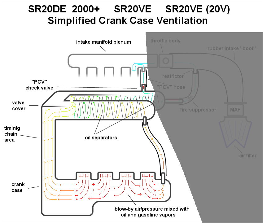
Here is another diagram showing the normal operation of the crank case ventilation system with half of the system greyed out:
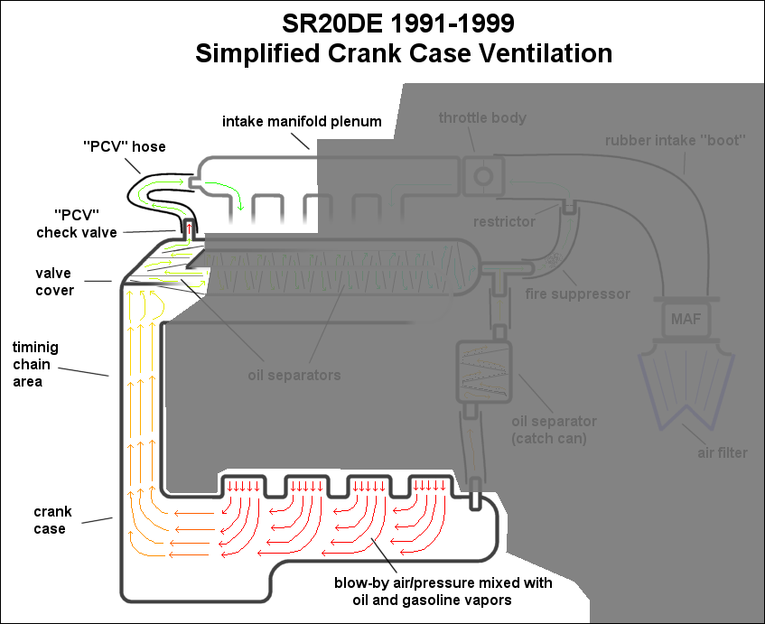
That pathway is used around 90% of the time you drive the car. A little blow-by is pushed into the crank case but the intake manifold sucks it up and the oil separator in the valve cover keeps most of the oil from escaping the engine. The manifold keeps a good vacuum on the crank case during idle and partial throttle conditions which amount to most of your driving.
"Okay Ben, what happens when you're at WOT then?"
I'm glad you asked.
That's where the other half of the system comes into play. Now there are a couple things happening at WOT.
Firstly, there is no real vacuum to speak of in the intake manifold or plenum. With the throttle fully open, the entire intake track experiences atmospheric pressure and no longer produces any vacuum. This means there won't be any vacuum applied to the crank case and blow-by evacuation will be problematic.
Secondly, WOT produces the most blow-by because of the pressure in the cylinder and the lack of vacuum in the crank case (remember the vacuum promotes ring seal and without good ring seal there is more blow-by).
This means there is a lot more blow-by to deal with at WOT and there's no vacuum to suck the blow-by up. In the past, OEMs just vented the crank case to atmosphere and called it a day. In these times of pollution consciousnesses, spouting air with oil and gasoline vapors into the atmosphere untreated is a big no-no. So in an effort to control those emissions Nissan routed the gasses back into the intake to take advantage of the slight vacuum present in the intake (very slight) and also route the pollutants back into the engine to be consumed and eventually treated by the catalytic converter.
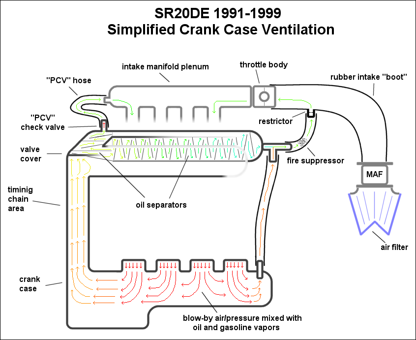
Because there is not really any vacuum present, the blow-by gasses build up pressure and relatively slowly move up to the valve cover via both the left and right pathways. These pathways are also larger than the regular PCV hose because flow is important now that the vacuum is gone.
Let's follow the path of the blow-bay gasses at WOT.
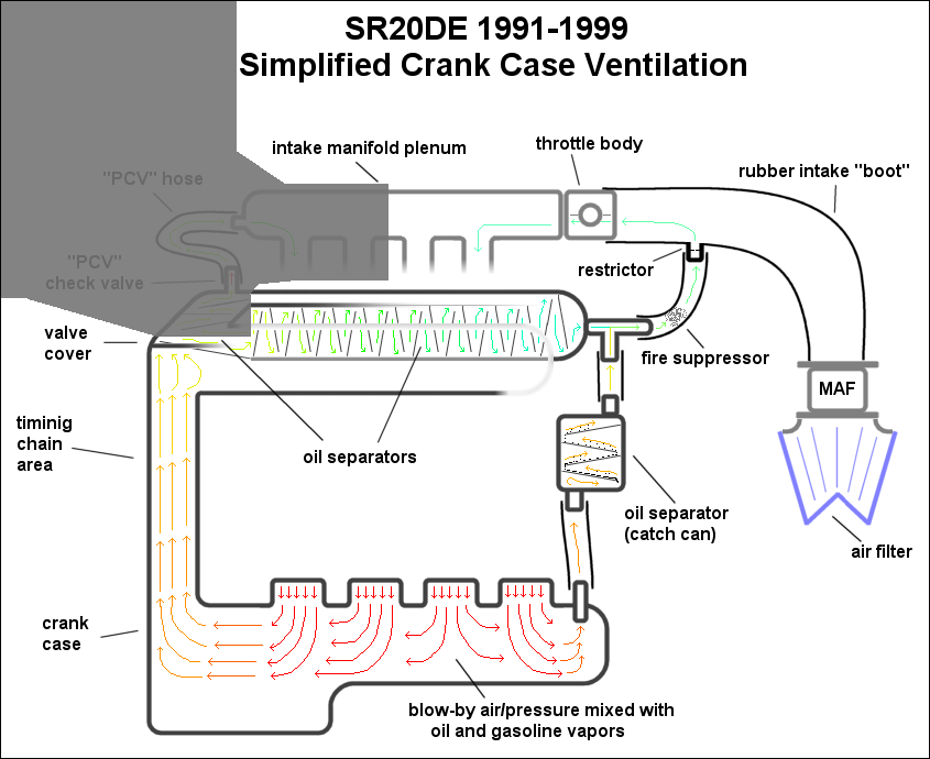
They start out at the bottom just as before and this time they go up the timing chain section and the catch can section on the right. The pressure in the crank case is now going to be about equal to that in the intake manifold, so not much of anything will flow through the PCV hose. The blow-by gasses will have to continue on through the valve cover where there is even more built-in oil separation labyrinth. Eventually the gasses leave the valve cover and meet up with the gasses that took the other route through the catch can. By now both routes have gone through an oil separator so the air is going to be relatively oil free.
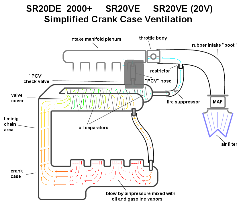
Here is another diagram showing this part of the system with the regular section greyed out:
Those are the basics of the 1991-1999 SR20DE crank case ventilation system. If you want to see what the passages in the valve cover actually look like, here is a great new thread by vorin that shows them: Opening up Valve Cover Air/Oil Separator
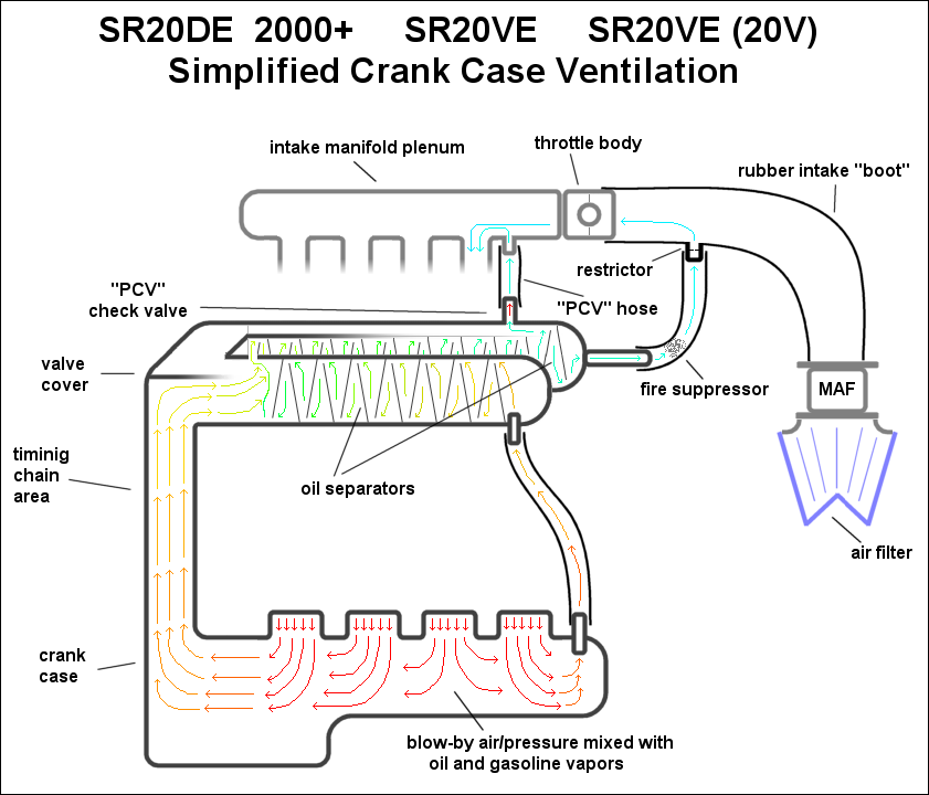
Continue reading for a thorough explanation of the roller rocker (years 2000+) SR20DE and SR20VE (including N1 and 20V) crank case ventilation system.
Grab yourself a beverage of your choice, sit back and relax. Keep reading to have all of your questions answered. If you came here looking for info on forced induction setups, read this N/A guide first then move on to https://www.sr20-forum.com/information-library/!42637-crank-case-ventilation-fully-explained-turbocharged-edition.html.
To understand what you're doing when you modify or repair the factory crank case ventilation system you should know how the factory systems works first before diving into modifying it or fixing it. It might also be nice to understand the history and evolution of the crank case ventilation system, so I'm going to start with the early SR20DE system and work up from there.
I know people like images so I won't hold off any longer.
Here's the factory system:

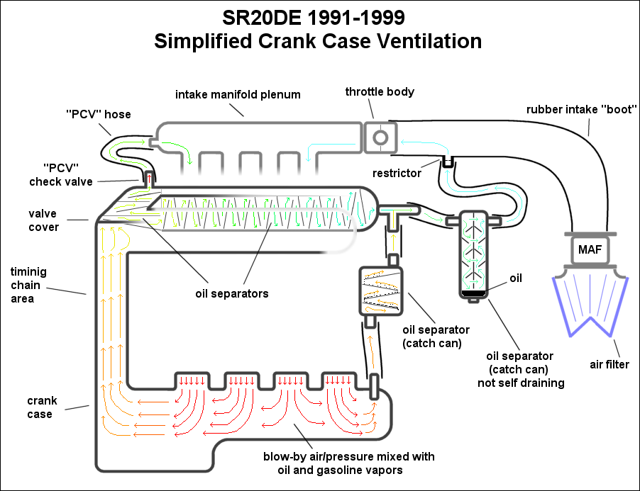
Now let me explain what's happening here. The piston rings don't seal perfectly, so there is some air that gets by them and we call that blow-by. This blow-by air is pressurized and will cause oil seals to fail and eventually will cause other major problems so it needs to be dealt with. Having a vacuum in the crank case is very good as it promotes ring seal and keeps windage losses (drag on the rotating crank caused by a cloud of oil in the crank case) to a minimum. Since having a vacuum in the crank case is good and having pressure there is bad, we must get rid of the pressure somehow.
The air comes in contact with a lot of oil in the crank case and basically turns into a mix of air and oil (along with a little bit of gasoline and water). This air/oil mix is represented by the red arrows in the crank case and as oil gets removed throughout the system I've made the color shift towards blue. I even showed little oil droplets condensing out of the air as it goes up through the "catch can" oil separator. I didn't show them everywhere in all the baffles, but you can imagine the same thing happening everywhere you see baffles.
The amount of air and oil can be quite significant, so Nissan put in two important pathways for the pressure to escape from the crank case because at times there can be a lot of air to evacuate.
On the left the air and oil can escape the crank case up along the timing chain portion of the block and into the valve cover. This is the usual pathway for the air to take.
On the right the oily air can escape the crank case (in times where there is excessive pressure to evacuate) through the provision in the side of the block, up through the oil separator (catch can) leaving the crank case.
So the goal is to have a vacuum in the crank case, and this is accomplished on some vehicles with a dry sump oil system, but on regular vehicles the intake manifold is used for the source of vacuum. Basically the engine is setup to consume it's own blow-by gasses. Not a super great idea because it coats the intake in oil residue and lowers the effective octane of your fuel, but it certainly is efficient, practical, and good for the environment.
How does blow-by lower your octane? Blow-by gasses with any amount of oil in them will lower the effective octane rating of your fuel because the vaporized oil will ignite at lower energy levels than 87 octane (R+M/2) gasoline. The more of it you allow to enter the cylinder, the more you will have to worry about detonation. This is usually not a big worry for naturally aspirated engines, but obviously forced induction is a different story.
All right if you've been paying attention we now have the blow-by gasses up and out of the crank case and in the valve cover now. The gasses are going to continue on through the small PCV (positive crank-case ventilation) port at the top-left corner of the valve cover which includes a one-way check valve so things can only flow out (and not in). The gasses flow out of the PCV port and into the intake manifold where they are sucked back into the engine to get consumed and pushed out of the exhaust. Simple enough.
Now the gasses have a bit of oil mixed in with it, so on it's way out of the valve cover it passes through a labyrinth of baffles designed to help condense the oil and collect the oil from the air. The more surface area the oil has to cling on to the more oil will separate from the air. The oil that is collected drains back down onto the valve train and eventually returns to the oil pan.
Here is another diagram showing the normal operation of the crank case ventilation system with half of the system greyed out:

That pathway is used around 90% of the time you drive the car. A little blow-by is pushed into the crank case but the intake manifold sucks it up and the oil separator in the valve cover keeps most of the oil from escaping the engine. The manifold keeps a good vacuum on the crank case during idle and partial throttle conditions which amount to most of your driving.
"Okay Ben, what happens when you're at WOT then?"
I'm glad you asked.
That's where the other half of the system comes into play. Now there are a couple things happening at WOT.
Firstly, there is no real vacuum to speak of in the intake manifold or plenum. With the throttle fully open, the entire intake track experiences atmospheric pressure and no longer produces any vacuum. This means there won't be any vacuum applied to the crank case and blow-by evacuation will be problematic.
Secondly, WOT produces the most blow-by because of the pressure in the cylinder and the lack of vacuum in the crank case (remember the vacuum promotes ring seal and without good ring seal there is more blow-by).
This means there is a lot more blow-by to deal with at WOT and there's no vacuum to suck the blow-by up. In the past, OEMs just vented the crank case to atmosphere and called it a day. In these times of pollution consciousnesses, spouting air with oil and gasoline vapors into the atmosphere untreated is a big no-no. So in an effort to control those emissions Nissan routed the gasses back into the intake to take advantage of the slight vacuum present in the intake (very slight) and also route the pollutants back into the engine to be consumed and eventually treated by the catalytic converter.
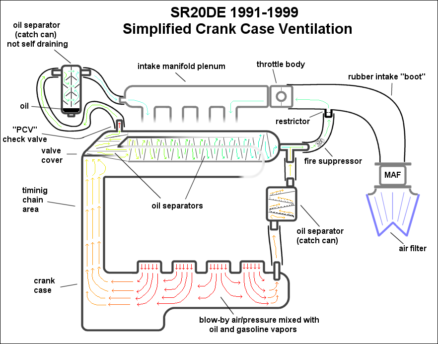
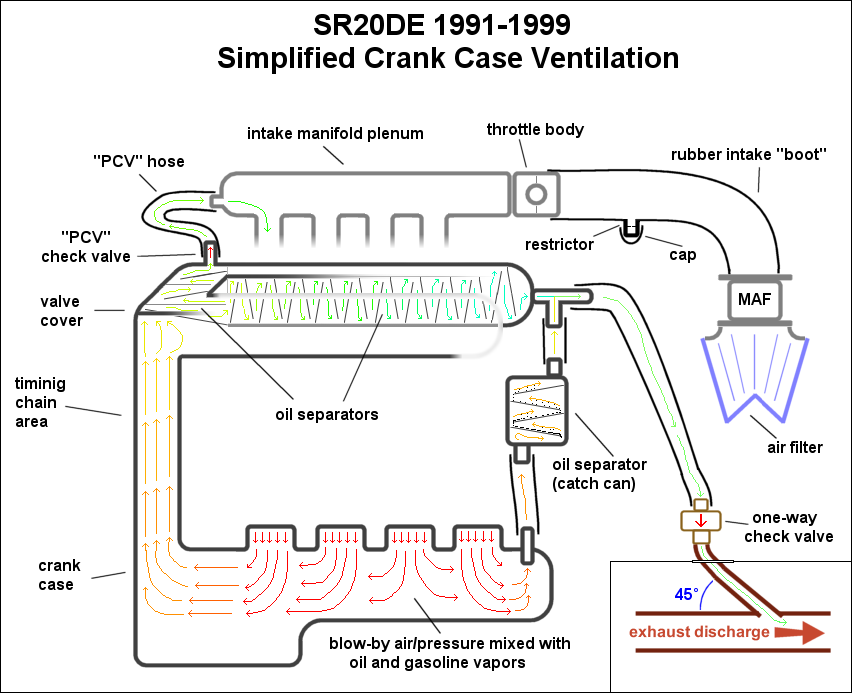
Because there is not really any vacuum present, the blow-by gasses build up pressure and relatively slowly move up to the valve cover via both the left and right pathways. These pathways are also larger than the regular PCV hose because flow is important now that the vacuum is gone.
Let's follow the path of the blow-bay gasses at WOT.
They start out at the bottom just as before and this time they go up the timing chain section and the catch can section on the right. The pressure in the crank case is now going to be about equal to that in the intake manifold, so not much of anything will flow through the PCV hose. The blow-by gasses will have to continue on through the valve cover where there is even more built-in oil separation labyrinth. Eventually the gasses leave the valve cover and meet up with the gasses that took the other route through the catch can. By now both routes have gone through an oil separator so the air is going to be relatively oil free.
Here is another diagram showing this part of the system with the regular section greyed out:

Those are the basics of the 1991-1999 SR20DE crank case ventilation system. If you want to see what the passages in the valve cover actually look like, here is a great new thread by vorin that shows them: Opening up Valve Cover Air/Oil Separator
Continue reading for a thorough explanation of the roller rocker (years 2000+) SR20DE and SR20VE (including N1 and 20V) crank case ventilation system.
Last edited by BenFenner
on 2018-09-21
at 07-08-05.


 Be the first to like this post.

 Back to top
