Welcome to the SR20 Community Forum - The Dash.
Register
SR20 forum logo

Thread: OBD2 -> OBD1 stepdown harness diagram

+ Reply To Thread
Posts: 51-60 of 87
2010-12-17 19:00:10
#51
Originally Posted by Cliff
Linking is fine. I'm on my phone right now so I'll respond later unless someone else chimes in


Thank you Cliff, greatly appreciate all your assistance!
2010-12-18 15:06:43
#52
Originally Posted by charleshsiao


Circuit diagrams - WRETCH

This is the consult plug that I have, and the pin info:

OBDI
(1). Rx (pin 7)
(2). Tx (pin 15)
(3). CLK (pin 14)
(4). 12V Ign (pin 38/47)
(5). GND (pin 39/48)
(6). CHK (pin 23?)

OBDII
(1). Rx (pin 64)
(2). Tx (pin 65)
(3). CLK (pin 68)
(4). 12V Ign (pin 56/61)
(5). GND (pin 10/43)
(6). CHK (pin ?)

Any info on this?

ps. strange that I can post any pictures ??... I double check that the url for my photo album definitely is working fine....??
(Same pic from sr20forum.com and some info: Consult plug pins. - SR20 Forum)
Apologes for referencing the link to sr20forum if this is not appropriate.....


Hi Cliff,
If I would want to include this into my stepdown adaptor I only need to conned:

OBDI
(1). Rx (pin 7)
(2). Tx (pin 15)
(3). CLK (pin 14)

to

OBDII
(1). Rx (pin 64)
(2). Tx (pin 65)
(3). CLK (pin 68)

Connection for no. (4). 12V Ign and (5). GND were already covered in your previous conversion table so I don't need to split and do the connection again?

Also if you have any info on (6). CHK that could further clearify (the link to sr20forum someone responded this CHK is not used for consult diagnostic).

Thanks again for your help!

Cheers,
2010-12-18 15:23:58
#53
My guess is that "chk" is referring to a loop check between the consult device and the ecu? In my mind, it's use is to determine whether the device should start communicating with the ecu or not?

I really don't know why the chk terminal pin is there, or what it's used for...
2011-02-06 04:29:51
#54
By the way, I saw some question about CONSULT but couldn't tell if the issue was ever resolved in this thread. The original spreadsheet didn't include it because I didn't need it. Here's the reference:

OBD1 ----- OBD2
14 --------- 68
15 --------- 65
7 --------- 64

It is in my forum but not in the project section of my main website.
2011-02-06 04:32:17
#55
Thanks, that is in fact the question that was raised. Appreciate the insight!
2011-05-13 07:44:57
#56
I noticed this is missing the EGR pinout. Any reason?

OBD1 ---> OBD2
8 EGR temperature sensor ---> 62 R/B EGR Temperature Sensor
2011-09-27 22:26:36
#57
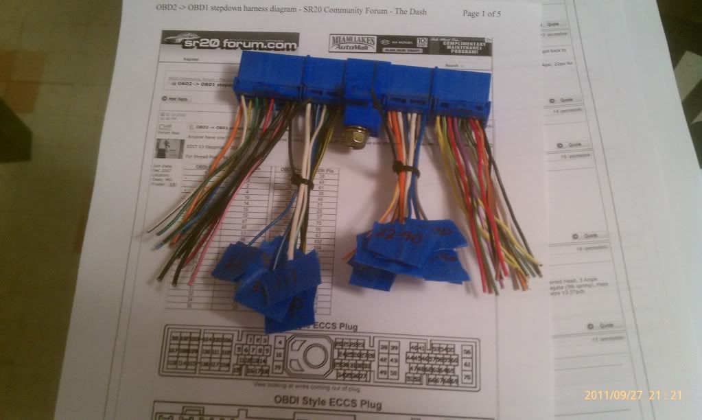
Back to this, I'm about to do the stepdown. When connecting the wires together im guessing solder is ok, unless im using magic to connect them to the B14 ecu side.Any other tips I should know prior to doing this...


thank you
2011-09-27 23:39:26
#58
You have to use solder, no other way.
2011-09-28 01:33:26
#59
Originally Posted by charleshsiao


Circuit diagrams - charleshsiao's Album - WRETCH

This is the consult plug that I have, and the pin info:

OBDI
(1). Rx (pin 7)
(2). Tx (pin 15)
(3). CLK (pin 14)
(4). 12V Ign (pin 38/47)
(5). GND (pin 39/48)
(6). CHK (pin 23?)

OBDII
(1). Rx (pin 64)
(2). Tx (pin 65)
(3). CLK (pin 68)
(4). 12V Ign (pin 56/61)
(5). GND (pin 10/43)
(6). CHK (pin ?)

Any info on this?

ps. strange that I can post any pictures ??... I double check that the url for my photo album definitely is working fine....??
(Same pic from sr20forum.com and some info: Consult plug pins. - SR20 Forum)
Apologes for referencing the link to sr20forum if this is not appropriate.....


Originally Posted by coalitionSE-L
By the way, I saw some question about CONSULT but couldn't tell if the issue was ever resolved in this thread. The original spreadsheet didn't include it because I didn't need it. Here's the reference:

OBD1 ----- OBD2
14 --------- 68
15 --------- 65
7 --------- 64

It is in my forum but not in the project section of my main website.


what about this info? or should i just use whats on the 1st page...


i guess this is the easy part, attaching wires to the ecu side will be the P.I.T.A.... lol

2011-09-28 03:01:57
#60
Man it's a painful process I spent couple days in the row doing it. Screwing it up, and redoing some wires.
+ Reply To Thread
  • [Type to search users.]
  • Quick Reply
    Thread Information
    There are currently ? users browsing this thread. (? members & ? guests)
    StubUserName

    Back to top