Welcome to the SR20 Community Forum - The Dash.
Register
SR20 forum logo

Thread: Shift Light

+ Reply To Thread
Posts: 31-40 of 52
2011-07-27 05:48:46
#31
Originally Posted by AaroNX
Is it going to be setup so that you can put the led's wherever you want? I assume you're presetting them to each users prefferred rpm, and we can use the button to change if needed? ...


Yup, this is exactly how it'll be However every time the car is shut off it will set to the default value...
2011-07-28 21:01:18
#32
This is awesome bro, do you have any for sale yet?? Please put me on the list!!
2011-07-30 22:41:28
#33
I went to the pick-n-pull this morning with a few friends - no SE-Rs! Last time I was there they had about three. Anyways, I pulled tach from an ugly convertible 240sx and made it fit in my cluster.

We have consistency and accuracy! Took long enough. This video shows the default threshold (2000 RPM so I don't have to rev my poor worn out car), the ability to turn off the light by holding the button for two seconds, and the ability to set the shift threshold by pressing the button once. My fingers are in the way for that...

[youtube]asYfGQgP_Tk[/youtube]

The board has three LED outputs. Two of them output a strobing signal to make the LEDs flash, and one of those two can be turned on and off by holding the button for two seconds. The third LED output just lights an LED solid when the threshold is reached.

I will put together a description of the kit, what will be included and some install instructions hopefully by tomorrow. I don't think there will be much demand, so I'll probably only make a couple kits, but I'll try to meet what little demand there is. People who showed interest from the beginning will have higher priority
2011-07-30 23:57:10
#34
I'm in for one..
2011-07-31 04:53:17
#35
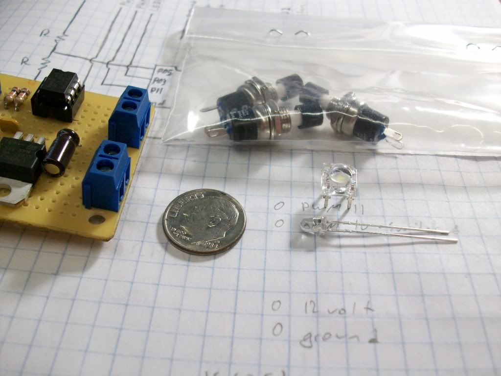
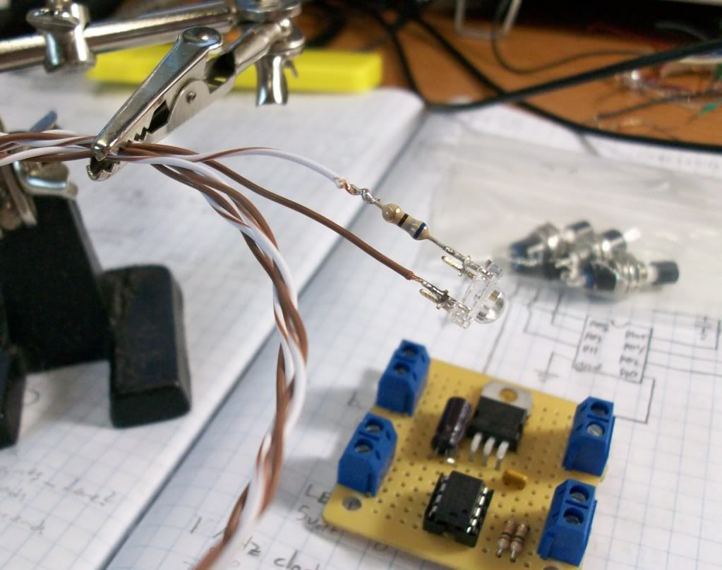
OKAY: Here's how it's going to be. The kit will include the main board, a nice pushbutton, and a few LEDs with resistors and wire already soldered in place. I have a few different styles of LEDs, and you can have any color you want, so long as that's white or red. I've already put up videos of the white, I'll put one of the red soon (tomorrow?).


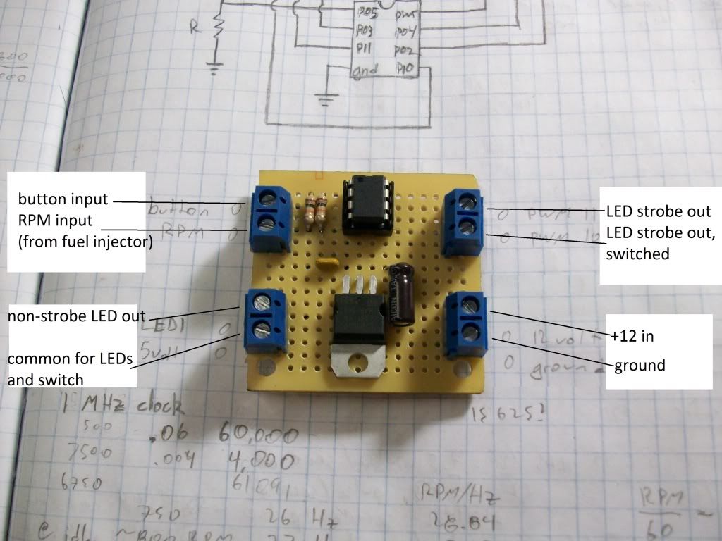
The main board has eight wire connections on it. They are:

+12 volts
ground

LED strobe out
LED strobe out, switched
LED non-strobe out

Button input
RPM input
+5 volts common for LED and switch

The +12 and ground connections are pretty self-explanatory. This power can be pulled from anywhere, though a switched supply would be best so this won't drain your battery.

There are three LED outputs. Three LEDs can be connected to this board at once. The ground side of the LED goes to one of the three outputs, and the positive sides go to the +5 volt common. Two of the outputs strobe when the RPM threshold is reached, and the third just goes on solid when the threshold is reached. One of the strobing outputs can be turned off using the pushbutton. Any one or combination of these outputs can be used, but only one LED per output.

One end of the button connects to the button input, the other side goes to the +5 volts common. The button has two functions – a short press (longer than 1/16th of a second) sets the current RPM as the new shift threshold. A long press (2 seconds or longer) turns on or off the switched LED strobe output.

The RPM input connects directly to one of the fuel injector wires. Each injector has a white wire and a colored wire. This input needs to be connected to one of the colored wires. Since each injector pulses once every 2 RPM, this is a really accurate method of measuring RPM. Now that this runs off of an injector, it should work on any car with fuel injection. However, I only have one car, a B13 SE-R, so this is the only car I can guarantee that this kit will work for.

The +5 volt connection is used as a common for the LEDs and the switch.

It is only necessary to dismantle the gauge cluster if you want to install LEDs in it. I will provide instructions for installing an LED below the cruise control light and in the tachometer needle, but the needle install is at your own risk. Beyond this, the installation is up to you. (Most everyone here is really creative anyways.)
2011-07-31 04:53:41
#36
The kit will basically include this, but the LEDs will be pre-wired with resistors and leads to connect to the board. The switch will also be pre-wired. No soldering will be required to install the kit unless you want a lit tach needle. I have three types of LEDs - the small 3mm LEDs in red only (bright but not super bright, good for the tach needle) and the larger square ones in white or red (very bright).

I'll upload a wiring schematic and some basic install instructions tomorrow

Last edited by petelite on 2011-07-31 at 05-00-07.
2011-07-31 15:05:20
#37
I'd prefer the larger square units, but it looks like they wouldn't install as neatly.

How long are you going to make the wires for the leds?
2011-07-31 16:42:35
#38
Originally Posted by AaroNX
I'd prefer the larger square units, but it looks like they wouldn't install as neatly.

How long are you going to make the wires for the leds?


I was thinking two feet? I can customize per order. Here's a pic of what the LED/resistor/wirelead combo will look like:


I should be able to take a few orders mid-week... I'll post here when I'm ready.
2011-07-31 17:44:21
#39
Subscribed!!!!!
2011-08-02 19:41:25
#40
Nice! If you hook it up to constant power, or a switch, couldn't the preferences(RPM) be saved?
+ Reply To Thread
  • [Type to search users.]
  • Quick Reply
    Thread Information
    There are currently ? users browsing this thread. (? members & ? guests)
    StubUserName

    Back to top