Whenever you have headwork done (install new valves, replace valves, seats, etc.) you must shim the valves to ensure that they are at the same height so that the rocker arm sits flat relative to the cam lobes. If this is not done, the cam will not contact the rocker squarely, leading to vibration and valve train wear. It was recommended to me by Sunbelt Performance Engines, a highly respected race engine builder, that this be done with the head torqued on the motor. The first thing that is needed is a measuring tool. Custom Steel sells a very nice one listed in this thread:
CS - Valve Shim Measuring Tool for serious engine builders - SR20 Forum
This item is very robust and should be a bit more accurate than the setup I used, which is probably a bit cheaper but you get what you pay for. Custom Steel's unit was not available when I started this project.
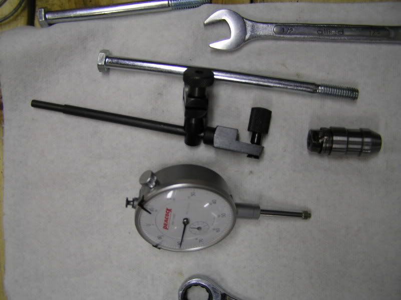
These are the parts: An HVLA lower shell with a 9/16 nut welded to the top (courtesy of Matt Kessler of Kessler Engineering,) a 6" long 9/16 bolt with a long shank, a measuring stand rod and a depth guage that reads to .001" (you can estimate the last .0001")
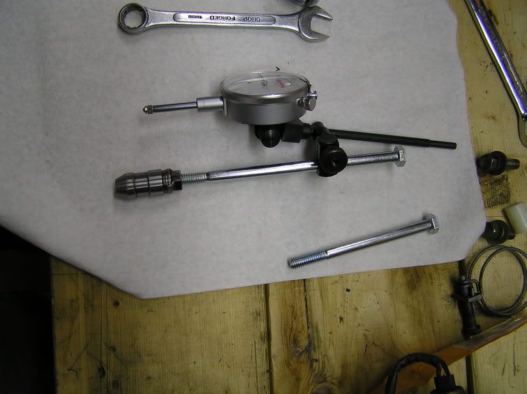
This is what it looks like assembled:
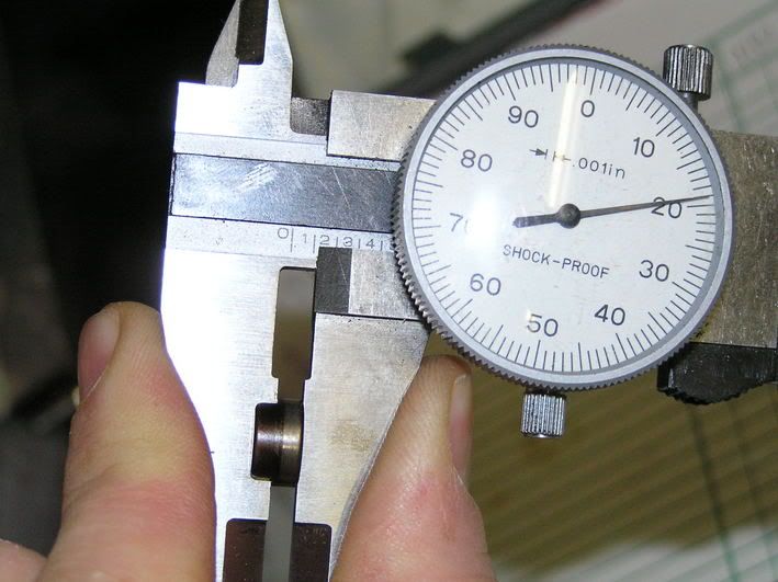
Next, measure all of your guides for thickness. The FSM says to use new guides, but I reused mine.
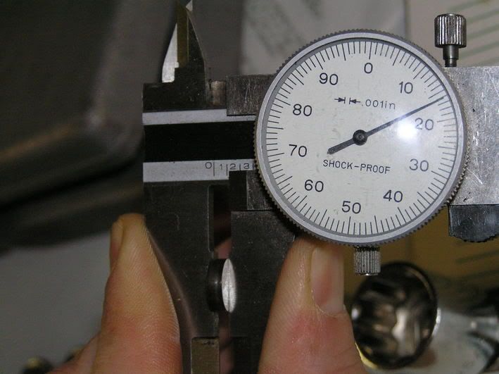
Now measure all of your shims. I have a couple of spare motors, so I had what I thought was a pretty good selection.
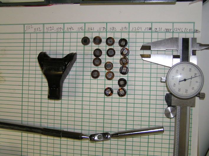
Lay out all of the guides and shims on a piece of graph paper, organizing them by thickness. As you can see, there are 17 different thicknesses of shims, from .1102" to .1260" in increments of .001". The guides are all supposed to be of the same height, but I had one that was .001" shorter than the rest. This picture shows my leftovers, but was fairly representative of the full original set. I had to use the flat side of a grinding wheel, followed by 2 grits of sandpaper to smooth it back out to get some of the shim heights I needed. For the shims I ground down myself, I made sure to only do one side and that side went modified side down towards the valve.
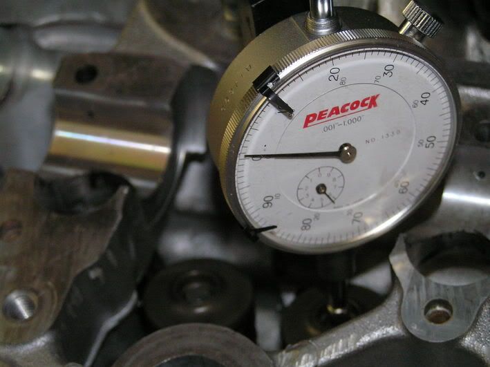
Now measure the heights of the valves without the guides or shims. Turn the graduated face of the dial to zero out the height of the first valve.
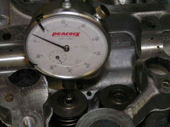
Now measure the second valve. The difference in height will be made up by using differing shim thicknesses. This one is .003" higher than the other, so I put a shim that was .003" shorter than the guide that went on the first valve to even things out.
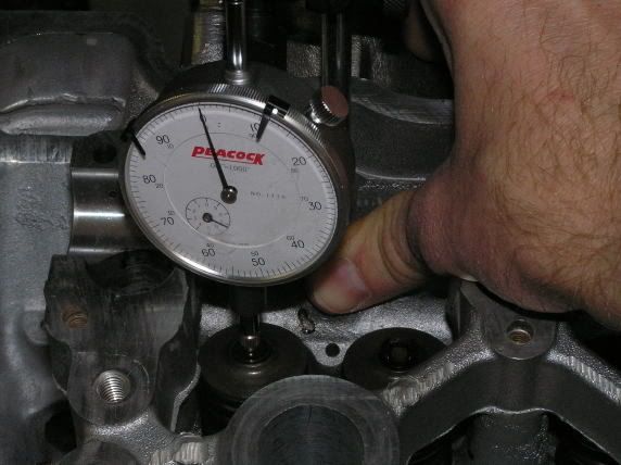
Now to make sure that everything came out correct, measure the final heights of the guide and shim topped valves. The FSM says to pull back gently on the stand portion of the measuring tool to take up any slop. The problem that I had with this method is that the harder you pull at the top of the rod or bolt, the more it bends and the more the reading changes. The true slop is generated due to the difference in the OD of the HVLA and the ID of the bore in which it sits. So, I just pushed down and back with my thumb at the top of the HVLA and no matter how hard I pushed, the reading on the dial stayed the same once the initial slack was taken up.
Dial zeroed out on the right valve:
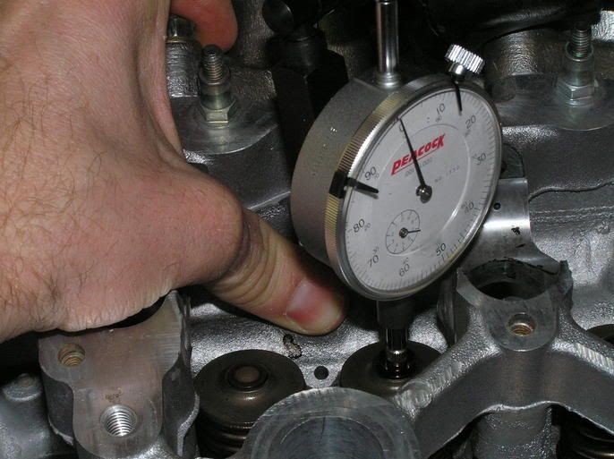
Dial is still at zero on the left valve:
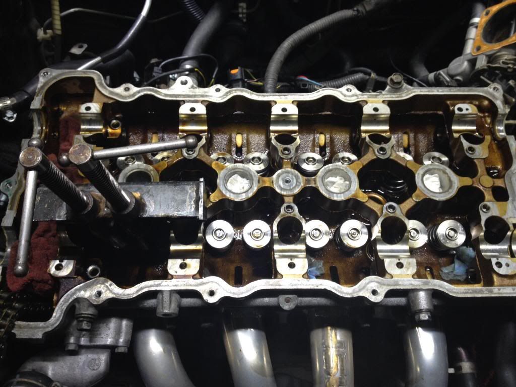
Now I'm ready to install the rockers and cams and finally put the motor back in the car!
CS - Valve Shim Measuring Tool for serious engine builders - SR20 Forum
This item is very robust and should be a bit more accurate than the setup I used, which is probably a bit cheaper but you get what you pay for. Custom Steel's unit was not available when I started this project.
These are the parts: An HVLA lower shell with a 9/16 nut welded to the top (courtesy of Matt Kessler of Kessler Engineering,) a 6" long 9/16 bolt with a long shank, a measuring stand rod and a depth guage that reads to .001" (you can estimate the last .0001")

This is what it looks like assembled:

Next, measure all of your guides for thickness. The FSM says to use new guides, but I reused mine.

Now measure all of your shims. I have a couple of spare motors, so I had what I thought was a pretty good selection.

Lay out all of the guides and shims on a piece of graph paper, organizing them by thickness. As you can see, there are 17 different thicknesses of shims, from .1102" to .1260" in increments of .001". The guides are all supposed to be of the same height, but I had one that was .001" shorter than the rest. This picture shows my leftovers, but was fairly representative of the full original set. I had to use the flat side of a grinding wheel, followed by 2 grits of sandpaper to smooth it back out to get some of the shim heights I needed. For the shims I ground down myself, I made sure to only do one side and that side went modified side down towards the valve.

Now measure the heights of the valves without the guides or shims. Turn the graduated face of the dial to zero out the height of the first valve.

Now measure the second valve. The difference in height will be made up by using differing shim thicknesses. This one is .003" higher than the other, so I put a shim that was .003" shorter than the guide that went on the first valve to even things out.

Now to make sure that everything came out correct, measure the final heights of the guide and shim topped valves. The FSM says to pull back gently on the stand portion of the measuring tool to take up any slop. The problem that I had with this method is that the harder you pull at the top of the rod or bolt, the more it bends and the more the reading changes. The true slop is generated due to the difference in the OD of the HVLA and the ID of the bore in which it sits. So, I just pushed down and back with my thumb at the top of the HVLA and no matter how hard I pushed, the reading on the dial stayed the same once the initial slack was taken up.
Dial zeroed out on the right valve:

Dial is still at zero on the left valve:

Now I'm ready to install the rockers and cams and finally put the motor back in the car!


 Back to top
