Before I get into anything instructional, if you do not know how to solder and/or have basic knowledge of electronics this mod may not be for you. In fact, even if you can handle this you may want to hit the junk yard and get a couple wiper switches to practice on.
I will not be held responsible if you ruin your shit, mmmkay?
BTW, this was done on a non-airbag B13. I can't say for sure what may or may not be different, but if you have an airbag this mod may not apply.
Go to Radio Shack and get:
10K Ohm 1/4-Watt Carbon Film Resistor (5-Pack) : Resistors | RadioShack.com
100K Dual-Ganged Stereo Volume Control - RadioShack.com (Actually any 100k ohm potentiometer will work. This one happened to be the smallest RS had.)
Control Knob : Control Knobs | RadioShack.com
1- Remove your steering column shroud
2- Remove your steering wheel
3- Unplug headlight/turn signal switch, wiper switch and cruise control if you have it
4- Three screws hold the switch body to the steering column, unscrew them and take the switch body to the nearest work bench

5- Turn switch over and locate four screws that hold the circuit board


6- Remove the screws and carefully lift board away from the switch body. Leave switch body upside down and move it to a safe place.
7- Turn circuit board over

8- Next to the black box you'll find a single, 36k ohm resistor. This resistor is responsible for the standard 5-6 second delay, it's location is responsible for the fixed delay. Unsolder and remove this resistor....


9- Directly to the left of the resistor you just removed will go a 10k ohm resistor. The lower value will drop delay to 2 seconds and the move to the left will unlock the magical variable function...


Please push the resistor all the way through and trim the leads off the bottom. That is a pic of one of my test boards.
10- There are two pads on the back of the board. Cut a length of speaker wire and solder to these two pads. Thinner wire will be easier to work with...


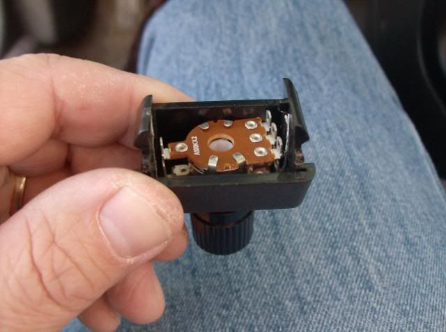
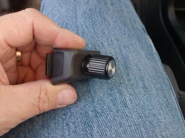
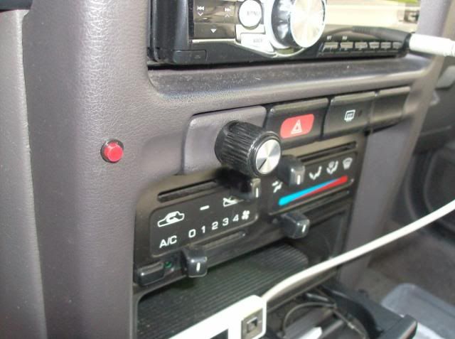
11- I mounted the volume control here...


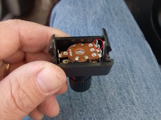
12- The speaker wire you soldered to the two pads on the back of the board will go to these terminals. The two I connected to are noted in this next pic, but depending on how you mount your volume control it may be different for you. One wire will always go to the center terminal, that is certain...

13- Put your car back together and enjoy the mod...
I'm still working on this. I've tried a couple adjustable stalks, one from an early Maxima and one from an early Altima but they didn't work. I believe this is due to the fact that their "value" is not compatible with the circuit board.
I will keep adding to/changing this as I make further progress.
I will not be held responsible if you ruin your shit, mmmkay?

BTW, this was done on a non-airbag B13. I can't say for sure what may or may not be different, but if you have an airbag this mod may not apply.
Go to Radio Shack and get:
10K Ohm 1/4-Watt Carbon Film Resistor (5-Pack) : Resistors | RadioShack.com
100K Dual-Ganged Stereo Volume Control - RadioShack.com (Actually any 100k ohm potentiometer will work. This one happened to be the smallest RS had.)
Control Knob : Control Knobs | RadioShack.com
1- Remove your steering column shroud
2- Remove your steering wheel
3- Unplug headlight/turn signal switch, wiper switch and cruise control if you have it
4- Three screws hold the switch body to the steering column, unscrew them and take the switch body to the nearest work bench

5- Turn switch over and locate four screws that hold the circuit board


6- Remove the screws and carefully lift board away from the switch body. Leave switch body upside down and move it to a safe place.
7- Turn circuit board over

8- Next to the black box you'll find a single, 36k ohm resistor. This resistor is responsible for the standard 5-6 second delay, it's location is responsible for the fixed delay. Unsolder and remove this resistor....


9- Directly to the left of the resistor you just removed will go a 10k ohm resistor. The lower value will drop delay to 2 seconds and the move to the left will unlock the magical variable function...


Please push the resistor all the way through and trim the leads off the bottom. That is a pic of one of my test boards.
10- There are two pads on the back of the board. Cut a length of speaker wire and solder to these two pads. Thinner wire will be easier to work with...


11- I mounted the volume control here...


12- The speaker wire you soldered to the two pads on the back of the board will go to these terminals. The two I connected to are noted in this next pic, but depending on how you mount your volume control it may be different for you. One wire will always go to the center terminal, that is certain...

13- Put your car back together and enjoy the mod...
I'm still working on this. I've tried a couple adjustable stalks, one from an early Maxima and one from an early Altima but they didn't work. I believe this is due to the fact that their "value" is not compatible with the circuit board.
I will keep adding to/changing this as I make further progress.
Last edited by SE-RMonkey
on 2012-05-15
at 21-30-30.


 Be the first to like this post.


 Back to top
