Welcome to the SR20 Community Forum - The Dash.
Register
SR20 forum logo

Thread: Finding a way to Reduce Oily Blow By Gases

+ Reply To Thread
Posts: 101-110 of 114
2009-05-11 03:12:46
#101
Originally Posted by canx2k
Vadim, how did this work for you, or did you end up going back to your writeup style?


Originally Posted by canx2k
My question is then is this also for NA systems, since he had a turbo in there, or am I better off with the writeup he posted elsewhere for my NA motor?


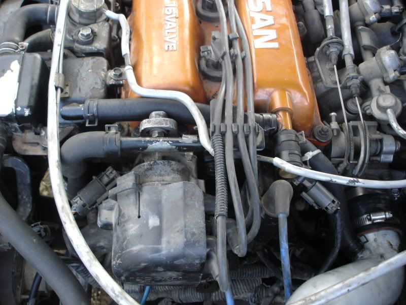
For NA I highly suggest you use the method in the writeup, I would use that method, but the DET's oil return line sticks out too much thus I can't fit a T and the stock separator.

I'm planning on it later on though. But so far I'm just running the hose, from the T and it still sucks in oil .

Originally Posted by Coheed
This setup will work flawlessly Vadim. You could also put an oil catch can in line with the clear hose from the T to the intake. Make sure the catch has a proper baffle system in there, and you can see the benefits of a proper setup.


The clear hose is a great way to see, but when it heats up it starts coming loose . I replaced it with a heater hose that is holding up a bit better.

I'm thinking if I should just buy an E-Bay catch can, or make one myself. I want to make one myself and make it fairly small, but you can't always get what you want right? haha
2009-05-11 03:14:58
#102
Originally Posted by insane
Not sure if i saw that mentioned in there. Didnt know there was a restrictor in there, is it where the 3 way tee is on the highports?


IF the highports have the restrictor, then it would be on the hose coming from that 3 way tee to the PCV valve on the valve cover. My experience has been with the lowports which have the restrictor.
2009-05-11 04:53:16
#103
Originally Posted by SER96VSPEC
IF the highports have the restrictor, then it would be on the hose coming from that 3 way tee to the PCV valve on the valve cover. My experience has been with the lowports which have the restrictor.


Low ports have a restrictor in the PCV and in the valve cover breather. Not exactly sure about the high ports hehe.

Either way those restrictors are as good as useless too
2009-05-12 16:31:40
#104
Got er' done. Took a while, and it's a bit tougher to make it look nice on a highport, but it's done. Will post a photo or two later.

Vadim, quick question, the tube that came off the top of my oil seperator had quite a bit of oil in it. is there a reason why that is? I though it's supposed to reduce oil, not make it more?

*edit* I also would like to make a small catch can after my pcv valve before it goes into the intake. Does it change the 'metered air inside the intake' if I add a small one inline, as long as it's a sealed system?
2009-05-12 18:57:34
#105
I gotta ask though, has anyone looked on the underside of their vc and seen what the routing of the 'L' tubes on the right side go to? why would nissan put fresh air into one part of the L and the other side to the intake? it just...doesn't make any sense?
2009-05-12 20:14:52
#106
Originally Posted by canx2k

*edit* I also would like to make a small catch can after my pcv valve before it goes into the intake. Does it change the 'metered air inside the intake' if I add a small one inline, as long as it's a sealed system?


Same here, I will be building one soon .

Originally Posted by canx2k
I gotta ask though, has anyone looked on the underside of their vc and seen what the routing of the 'L' tubes on the right side go to? why would nissan put fresh air into one part of the L and the other side to the intake? it just...doesn't make any sense?


Uhhh something is not right there!

Both of those should connect to your Intake Manifold!
2009-05-12 20:33:37
#107
no, that's not what I mean - the top of the oil catch can goes to one of the nipples off the valve cover, the other nipple goes to the intake, between the maf and the tb. What I dont get is why nissan put the clean air coming off the catch can to one of the nipples that oil gets splashed into? Does the head need that clean air to cycle through the vc before it goes to the cai?
2009-05-13 01:04:08
#108
Photoz up - almost looks stock.
had to ziptie the hose to one side though, otherwise the throttle arm catches.

2009-05-13 04:39:08
#109
Aha! Well there is a reason to why they run it to the intake. It doesn't know that it's clean air, or does it mater. When your driving the car is sucking in the blow by gasses from the valve cover. Note that the clean air does not go into the valve cover.

What I don't get is the catch can design. Which I forgot to answer in my earlier quote. It is normal to have oil on it. I would wash it (stock catch can) out with some carb cleaner, or something else that can wash oil away.

Now back to why the design makes no sense. Our valve covers have a T, one to the intake other to the catch can then to the block. so the oil drips from one side of the T to the catch can, which then it just drips back to the block. So technically running a straight line from the T to the block would work.

Now for the RR and VE, they got rid of the catch can, or at least put it inside the valve cover. So then there is a straight line to the block.
2009-05-13 15:49:42
#110
Originally Posted by Vadim


Vadim, why not just use the factory T instead of capping it in one place and then adding a T somewhere else? Seems to me that it would look better and install cleaner if you just connected the factory tube (the one that runs from the T between the VC and the Dist) to the block tube, and run your vac source off the other side of the valve cover T...

Also, where did you find that weld in bung for your barb fitting?
+ Reply To Thread
  • [Type to search users.]
  • Quick Reply
    Thread Information
    There are currently ? users browsing this thread. (? members & ? guests)
    StubUserName

    Back to top