Welcome to the SR20 Community Forum - The Dash.
Register
SR20 forum logo

Thread: B13 variable intermittent wiper mod? YES!

+ Reply To Thread
Posts: 31-40 of 103
2012-03-30 15:54:45
#31
Originally Posted by eggman
wow is that seat pass through?
cool

So I am understanding that the wiper stalk will be just plug and play?


You mean the seat is 60/40 foldable? Yes...

Yes this is plug and play. I'll take a pic of the back of an ordinary switch for you guys to compare
2012-03-30 16:13:59
#32
Originally Posted by eggman
....So I am understanding that the wiper stalk will be just plug and play?


Note: I may be wrong, but I don't think the PHDM B13's came with cruise control. If you have cruise control your wiper switch body will have terminals that contact the back of the steering wheel. If you want to keep your CC it appears from the pics that you could simply swap the PHDM stalk and circuit board over to your USDM switch body. I've removed and replaced the stalk and board from a USDM switch and it's a piece of cake.
2012-03-30 16:17:54
#33
Originally Posted by datsun_sky
You mean the seat is 60/40 foldable? Yes...

Yes this is plug and play. I'll take a pic of the back of an ordinary switch for you guys to compare


Originally Posted by SE-RMonkey
Note: I may be wrong, but I don't think the PHDM B13's came with cruise control. If you have cruise control your wiper switch body will have terminals that contact the back of the steering wheel. If you want to keep your CC it appears from the pics that you could simply swap the PHDM stalk and circuit board over to your USDM switch body. I've removed and replaced the stalk and board from a USDM switch and it's a piece of cake.


Damn I want a seat like that!
I would love a stalk too.
Can you get your hands on any more of these? Maybe me and monkey can get them shipped together to the US
2012-03-31 22:43:35
#34
Damn, so close! I did manage to mount the Maxima stalk in the B13 switch body. Then based on the pic of the back of the PHDM switch I tried wiring it up, but I can't get the variable delay to work....


Somthing(s) must be different on the circuit boards.
2012-03-31 23:12:31
#35
SER Monkey,have you looked at the altima switches?
maybe an altima around that era(u13?) would be more compatible than a Maxima??
2012-03-31 23:37:23
#36
Originally Posted by eggman
SER Monkey,have you looked at the altima switches?
maybe an altima around that era(u13?) would be more compatible than a Maxima??


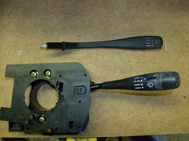
Out of all the Nissan's of the era, the B13 set up is unique. It uses an amplifier built into the switch. Other models use a separate plug in type amplifier for the delay and others use the time control unit for the delay. Rockauto.com has pics of them all and the B13 switch body itself is unique as it houses the amplifier circuit.

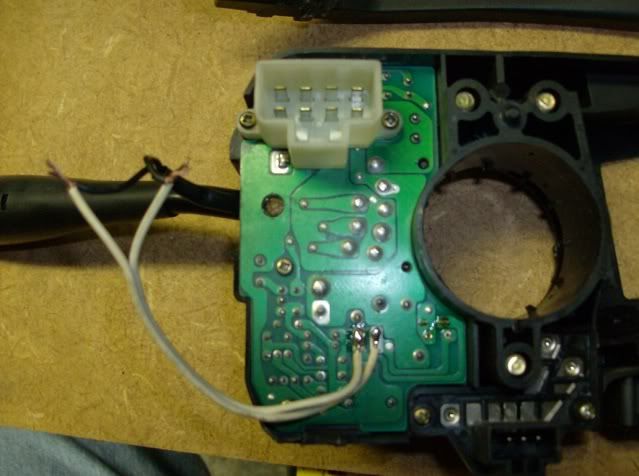
Once I get my hands on a PHDM switch I'll compare the circuit board to the USDM board and hopefully come up with a "dirty" mod.

As I originally stated, I'm on a mission.
Last edited by SE-RMonkey on 2012-03-31 at 23-55-53.
2012-04-02 01:29:43
#37
@SE-R Monkey you are correct, in PI there is no cruise control. Nice try on tapping the 2 wires. i thought it will run as stock. since failed, there is really something unique with the board.... let see what i can do...
2012-04-02 20:26:49
#38
Originally Posted by datsun_sky
@SE-R Monkey you are correct, in PI there is no cruise control. Nice try on tapping the 2 wires. i thought it will run as stock. since failed, there is really something unique with the board.... let see what i can do...


If it's not to much trouble I'd love to see a few pics of the back side of the board.
2012-04-03 01:10:53
#39
Originally Posted by SE-RMonkey
If it's not to much trouble I'd love to see a few pics of the back side of the board.


so you mean you want me to dismantle the board

ok, the holy week is coming so probably i can do that for you... by simply clicking the "thanks" button will do for me
Last edited by datsun_sky on 2012-04-03 at 01-37-29.
2012-04-03 02:24:20
#40
Originally Posted by datsun_sky
so you mean you want me to dismantle the board ...


There are four screws that hold it into the body. Remove them, lift the board, snap a couple pics and put it back together... but only if you're comfortable doing it.
+ Reply To Thread
  • [Type to search users.]
  • Quick Reply
    Thread Information
    There are currently ? users browsing this thread. (? members & ? guests)
    StubUserName

    Back to top