You can use just water with the right nozzle works best.
Recently my car puts down 585whp at 29lbs (dynojet , not the usual dynomite(prob 540-50whp) ) on just water and race fuel.
If you want I can give you some guidance.
We have been working with meth water some years know... there may kits on the market but only a few have the right one.Personally the snow and evil are cheap and works very well .Im going to use the aquamist hf5 in my new proyect.
Here its a good reading.
It is my attempt of explaining how different type of systems work and its advantage and dis-advantage, based on current systems offered. It is a my view and findings, please do chime in and discuss.
1) Single-stage
2) Two-stage
3) Progressive Pump Speed system (PPS)
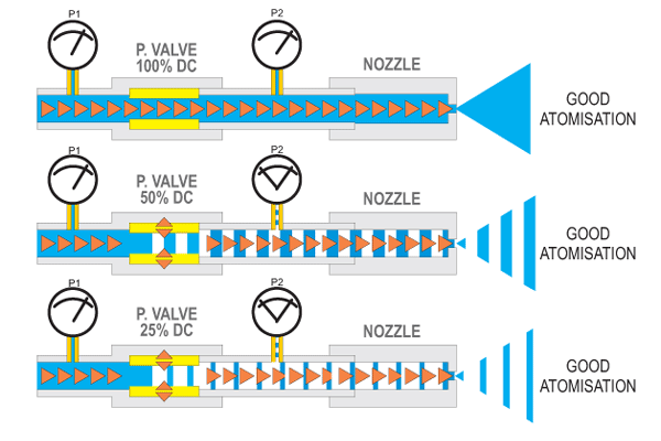
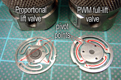
4) PWM Valve controlled system
5) System that will integrate well with third party controllers.
6) Direct port
The single stage:
The single stage WAI (water alcohol injection), as the heading implies, is not as basic as most people expects. It some cases, it will out perform a two-dimension progressive system. Please do not underestimate it. I will try to explain briefly why after the next few paragraphs.
Having a single trigger point and a fixed flow rate, one will get to know its effect on your engine very quickly. Due to its consistent repeatability, it is very easy to tune. This type of system is normally set to start spray in the peak torque region, where the engine is most likely to knock.
As the RPM climbs, the ratio of water to mass air tends to decrease. This may not be a bad thing because the tendency to knock is also lessen as the wastegate starts to open and prevent the boost pressure from increasing further. The volumetric efficiency of the engine also decreases as RPM climbs, breathing in less air. This also has the effect of reducing the engine's tendency to knock, demand of WAI flow is less. Unfortunately some engines do require continuous WAI flow at higher RPM due to heat build up through friction and turbo efficiency.
A 2-D pump speed system based on manifold pressure is a little bit tricky to tune compared to the single stage system. The user has to set the start and finish pressure points, those points are sometimes set at a considerable distance apart. Matching those operation points in a 3-D environment such as RPM/Boost ramp (nonlinear) is quite difficult. We will be discussing it in more details later.
FOR:
1) Low cost, simple and dependable.
2) Easy to tune
3) Very effective on a stock factory set up with a few pounds of boost extra.
AGAINST:
1) Dynamic operating range is narrow, may not be as effective on a high RPM knock suppression.
2) For high power/ high % alcohol applications, considerable fuel has to be taken out (boost clamp) to make the afr tolerable. Some sort of failsafe mechanism is necessary to prevent engine destruction when the WAI fails to delivery the correct flow.
END
The 2-stage system
(2nd September 2007)
At present, adding a second manifold pressure switch to active an additional solenoid valve at a higher manifold pressure is the definition of a 2-stage system.
This arrangement gives the system greater flexibility as well as extending the flow range. It addresses the problem associated with the single stage system, too much flow at the start and not enough when RPM climbs beyond the wastegate setting.
As the system is based on boost trigger, it still won?t address the RPM related flow. For a turbo charge engine, the most significant active regions are the boost ramping stage and engine?s maximum torque range. A two-stage system fits these two regions nicely, allowing the some form of cooling demand during the ramp-up stage. The second stage provides the in-cylinder cooling and knock suppression as the engine is under the most stress or highest BMEP (Brake Mean Effective Pressure).
FOR:
1) Relatively low cost to give mark improvement to the single-stage system.
2) Provides well defined triggering points during the boost cycle.
3) Minimising the under/over flow problem.
AGAINST:
1) Trigger points requires some time to set up.
2) Triggering points may differ on each gear if you have a fast spool up turbo
3) Require a bit more care during tuning
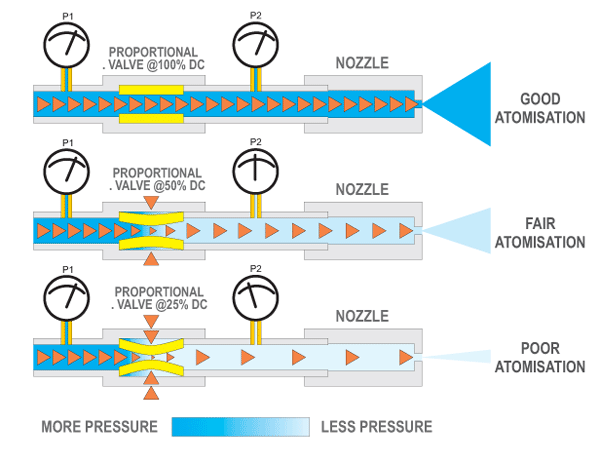
Propressive Pump Speed system (PPS)
(2nd September 2007)
Does the pump speed controller perform better than a two-stage system, you are about to find out.
Changing pump speed merely put more pressure behind a nozzle, hence more flow. This type of system is commonly known as a progressive system (pump-speed).
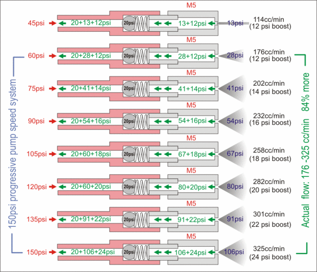
Let us examine how much a M5 nozzle will flow between 40psi to 160psi. According the chart below (Published by Hago, a well know US oil heater nozzle manufacturer), the flow starts from 200cc/min and ends at 400cc/min., when pressure is increased from 40psi to 160 psi.
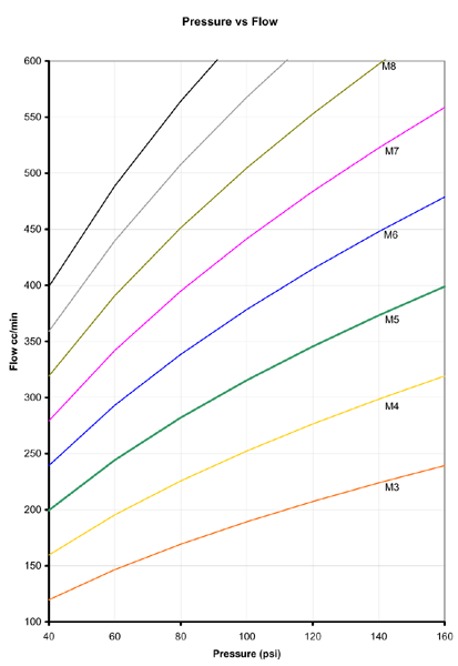
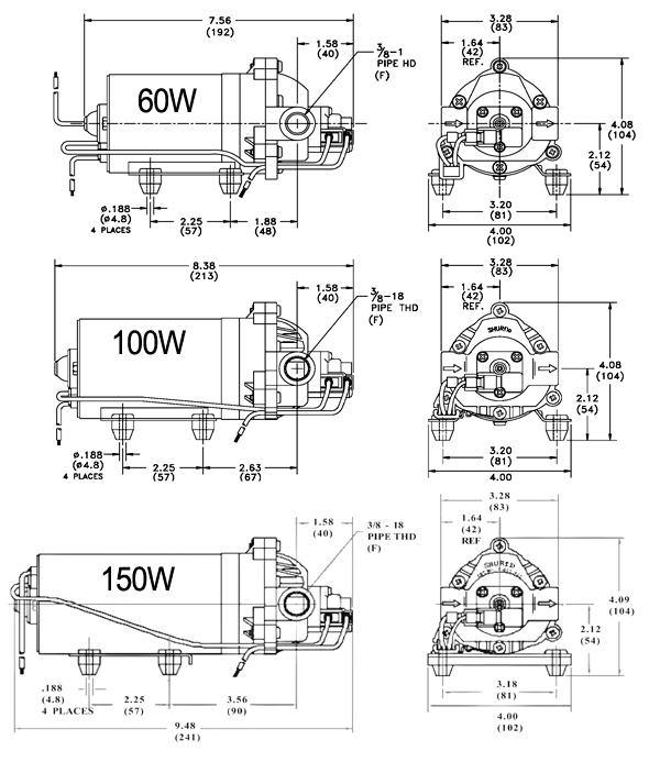
Almost all PWM pump controller on the market uses Shurflo pump, designed to operate between 0-150psi. The heart of the system is an electronic motor speed controller, vary the speed according to a sensor. It could be a MAP sensor, a MAF or any sensors that read engine load. It is normally a 2-dimensional system. A manifold-pressure type system does not take into account of any RPM change.
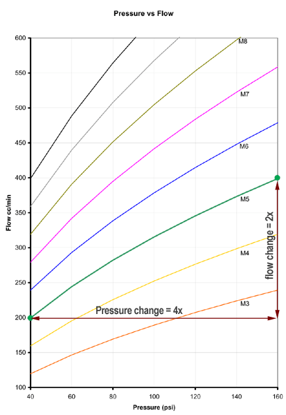
A swirling type atomising nozzle requires a head pressure of at least 30psi to produce a decent mist. Droplet size is very important to the inlet cooling ability and even cylinder distribution. Let say the system pressure starts at 40psi (as shown on the chart) and ends at 160psi. One can assume you will get a 4x flow range? In practice, not so, according to the chart, you will only get a flow change from 200cc/min to 400cc.min (see M5) instead of 200cc/min to 800cc/min. Flow/pressure obeys the square-root law.
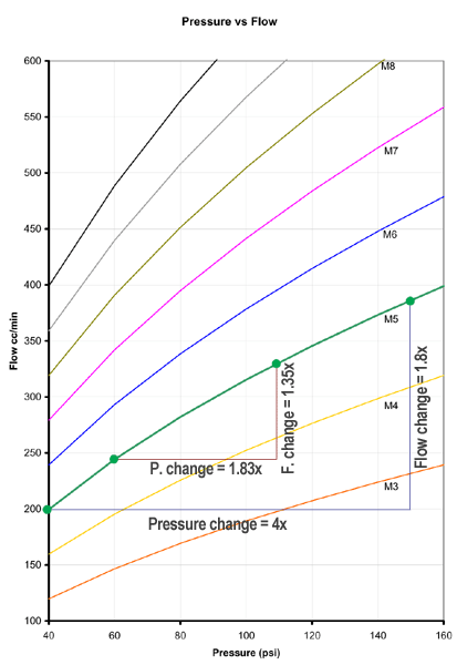
Being "progressive" implies a reasonable dynamic range between start and finish. How progressive? Almost no one ever questions this. Most people just assumes it covers all the flow requirement between 10psi to 20 psi of boost once the range-dials are set on their pump speed controller. In practice, you cannot expect the same M5 nozzle will serve a wider operating range between 5-25psi by merely changing the dial, the range is governed by the law of physics and not a technically advanced motor speed controller.
If one would want to delve deeper into the subject, as the title demands. So the subject will continue?
Just to recap, good dynamic range (pressure/flow span) is the main factor one should expect from a "progressive" WIA system. Let see what a 150psi system can really offer. We shall take into account of the effect of manifold pressure, inline checkvalve as well as minimum pressure for a good atomised spray.
For example:
1) Manifold pressure start: 10psi
2) Manifold pressure ends: 20psi
3) Inline checkvalve crack pressure: 30psi
4) Minimum pressure of the atomising nozzle: 30psi.
When the system starts: it will instantly see an initial back-pressure of 60psi and a final back-pressure of 70psi (extra manifold pressure). The actual dynamic pressure range is now from 60psi to 110psi. The system can now only manage a 35% change in flow, far from one would imagine a 150psi pump system should perform.
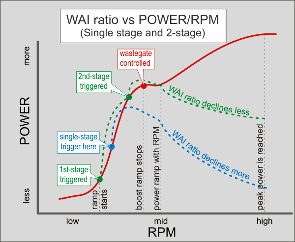
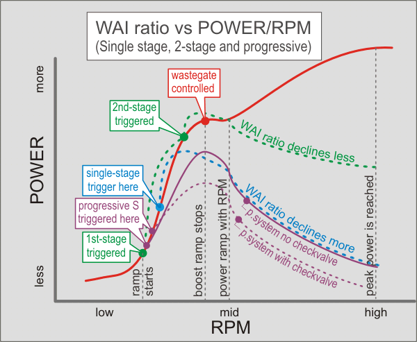
There are other factors that could also affect the performance of the 2-D progressive pump system. It may be a subject for a later discussion, depending on the interest of the readers. Chart below is a predicted performance of a progressive system compared to a single and two-stage system. I hope there will be people chiming in to add to this. At first glance, it doesn't appear there is a distinct advantage for adding a progressive controller. Adding a bigger nozzle doesn't alter the dynamic range, it just shifts the whole curve higher.
FOR:
1) Easy to set the start and end point.
2) Some correlation between manifold pressure and flow
3) Cost effective.
AGAINST:
1) Limited dynamic range, system becomes less effective after wastegate pressure. (see addendum)
2) Extra cost can easily be spent on a higher performance two-stage system with greater dynamic range .
3) If the 2-D system is used to replace high % fuel with alcohol, re-mapping the 3-D fuel map will be very difficult due to the wide dynamic flow range demanded by the engine.
4) Pulsing due to demand switch ~20psi ripple. (some system by-pass this switch, but risking system pressure beyond design limits). May require further explaination
5) Response time due to inertia of a rotating - laggy (start) and over-run (stop). May require further explaination
Recently my car puts down 585whp at 29lbs (dynojet , not the usual dynomite(prob 540-50whp) ) on just water and race fuel.
If you want I can give you some guidance.
We have been working with meth water some years know... there may kits on the market but only a few have the right one.Personally the snow and evil are cheap and works very well .Im going to use the aquamist hf5 in my new proyect.
Here its a good reading.
It is my attempt of explaining how different type of systems work and its advantage and dis-advantage, based on current systems offered. It is a my view and findings, please do chime in and discuss.
1) Single-stage
2) Two-stage
3) Progressive Pump Speed system (PPS)
4) PWM Valve controlled system
5) System that will integrate well with third party controllers.
6) Direct port
The single stage:
The single stage WAI (water alcohol injection), as the heading implies, is not as basic as most people expects. It some cases, it will out perform a two-dimension progressive system. Please do not underestimate it. I will try to explain briefly why after the next few paragraphs.
Having a single trigger point and a fixed flow rate, one will get to know its effect on your engine very quickly. Due to its consistent repeatability, it is very easy to tune. This type of system is normally set to start spray in the peak torque region, where the engine is most likely to knock.
As the RPM climbs, the ratio of water to mass air tends to decrease. This may not be a bad thing because the tendency to knock is also lessen as the wastegate starts to open and prevent the boost pressure from increasing further. The volumetric efficiency of the engine also decreases as RPM climbs, breathing in less air. This also has the effect of reducing the engine's tendency to knock, demand of WAI flow is less. Unfortunately some engines do require continuous WAI flow at higher RPM due to heat build up through friction and turbo efficiency.
A 2-D pump speed system based on manifold pressure is a little bit tricky to tune compared to the single stage system. The user has to set the start and finish pressure points, those points are sometimes set at a considerable distance apart. Matching those operation points in a 3-D environment such as RPM/Boost ramp (nonlinear) is quite difficult. We will be discussing it in more details later.
FOR:
1) Low cost, simple and dependable.
2) Easy to tune
3) Very effective on a stock factory set up with a few pounds of boost extra.
AGAINST:
1) Dynamic operating range is narrow, may not be as effective on a high RPM knock suppression.
2) For high power/ high % alcohol applications, considerable fuel has to be taken out (boost clamp) to make the afr tolerable. Some sort of failsafe mechanism is necessary to prevent engine destruction when the WAI fails to delivery the correct flow.
END
The 2-stage system
(2nd September 2007)
At present, adding a second manifold pressure switch to active an additional solenoid valve at a higher manifold pressure is the definition of a 2-stage system.
This arrangement gives the system greater flexibility as well as extending the flow range. It addresses the problem associated with the single stage system, too much flow at the start and not enough when RPM climbs beyond the wastegate setting.
As the system is based on boost trigger, it still won?t address the RPM related flow. For a turbo charge engine, the most significant active regions are the boost ramping stage and engine?s maximum torque range. A two-stage system fits these two regions nicely, allowing the some form of cooling demand during the ramp-up stage. The second stage provides the in-cylinder cooling and knock suppression as the engine is under the most stress or highest BMEP (Brake Mean Effective Pressure).
FOR:
1) Relatively low cost to give mark improvement to the single-stage system.
2) Provides well defined triggering points during the boost cycle.
3) Minimising the under/over flow problem.
AGAINST:
1) Trigger points requires some time to set up.
2) Triggering points may differ on each gear if you have a fast spool up turbo
3) Require a bit more care during tuning
Propressive Pump Speed system (PPS)
(2nd September 2007)
Does the pump speed controller perform better than a two-stage system, you are about to find out.
Changing pump speed merely put more pressure behind a nozzle, hence more flow. This type of system is commonly known as a progressive system (pump-speed).
Let us examine how much a M5 nozzle will flow between 40psi to 160psi. According the chart below (Published by Hago, a well know US oil heater nozzle manufacturer), the flow starts from 200cc/min and ends at 400cc/min., when pressure is increased from 40psi to 160 psi.
Almost all PWM pump controller on the market uses Shurflo pump, designed to operate between 0-150psi. The heart of the system is an electronic motor speed controller, vary the speed according to a sensor. It could be a MAP sensor, a MAF or any sensors that read engine load. It is normally a 2-dimensional system. A manifold-pressure type system does not take into account of any RPM change.
A swirling type atomising nozzle requires a head pressure of at least 30psi to produce a decent mist. Droplet size is very important to the inlet cooling ability and even cylinder distribution. Let say the system pressure starts at 40psi (as shown on the chart) and ends at 160psi. One can assume you will get a 4x flow range? In practice, not so, according to the chart, you will only get a flow change from 200cc/min to 400cc.min (see M5) instead of 200cc/min to 800cc/min. Flow/pressure obeys the square-root law.
Being "progressive" implies a reasonable dynamic range between start and finish. How progressive? Almost no one ever questions this. Most people just assumes it covers all the flow requirement between 10psi to 20 psi of boost once the range-dials are set on their pump speed controller. In practice, you cannot expect the same M5 nozzle will serve a wider operating range between 5-25psi by merely changing the dial, the range is governed by the law of physics and not a technically advanced motor speed controller.
If one would want to delve deeper into the subject, as the title demands. So the subject will continue?
Just to recap, good dynamic range (pressure/flow span) is the main factor one should expect from a "progressive" WIA system. Let see what a 150psi system can really offer. We shall take into account of the effect of manifold pressure, inline checkvalve as well as minimum pressure for a good atomised spray.
For example:
1) Manifold pressure start: 10psi
2) Manifold pressure ends: 20psi
3) Inline checkvalve crack pressure: 30psi
4) Minimum pressure of the atomising nozzle: 30psi.
When the system starts: it will instantly see an initial back-pressure of 60psi and a final back-pressure of 70psi (extra manifold pressure). The actual dynamic pressure range is now from 60psi to 110psi. The system can now only manage a 35% change in flow, far from one would imagine a 150psi pump system should perform.
There are other factors that could also affect the performance of the 2-D progressive pump system. It may be a subject for a later discussion, depending on the interest of the readers. Chart below is a predicted performance of a progressive system compared to a single and two-stage system. I hope there will be people chiming in to add to this. At first glance, it doesn't appear there is a distinct advantage for adding a progressive controller. Adding a bigger nozzle doesn't alter the dynamic range, it just shifts the whole curve higher.
FOR:
1) Easy to set the start and end point.
2) Some correlation between manifold pressure and flow
3) Cost effective.
AGAINST:
1) Limited dynamic range, system becomes less effective after wastegate pressure. (see addendum)
2) Extra cost can easily be spent on a higher performance two-stage system with greater dynamic range .
3) If the 2-D system is used to replace high % fuel with alcohol, re-mapping the 3-D fuel map will be very difficult due to the wide dynamic flow range demanded by the engine.
4) Pulsing due to demand switch ~20psi ripple. (some system by-pass this switch, but risking system pressure beyond design limits). May require further explaination
5) Response time due to inertia of a rotating - laggy (start) and over-run (stop). May require further explaination
 Be the first to like this post.