Welcome to the SR20 Community Forum - The Dash.
Register
SR20 forum logo

Thread: Intake Manifold Hose Connections

+ Reply To Thread
Posts: 21-30 of 35
2008-10-14 17:37:01
#21
Originally Posted by Andreas
.

The 1/2 inch pipe listed To Intake that goes to the bottom BOV housing is the the air feed hose to The Idle control, AC regulator and Cold Start valve


what i was just trying to state is that the 1/2in hose right by the throttle body does not go on top of the BOV diaphram, it may go to the pipe the BOV is mounted on but does not go on top of the BOV diaphram, that was all i was trying to say.
2008-10-14 17:38:49
#22
Originally Posted by Vadim
Picture updated to further clearify what goes where. Please do a hard refresh on your browser window (CTRL + F5).

Thanks!


this was my problem lol, i was seeing two things that said BOV, so i was confused
2008-10-14 18:01:59
#23
Originally Posted by carfreak240
this was my problem lol, i was seeing two things that said BOV, so i was confused


See you were seeing the newer picture while Miko was seeing even older picture.

But now it should be good, I will do a better picture when I get back
2008-10-14 18:56:25
#24
Originally Posted by Andreas
This 1/2in hose must go from intake manifold to any where between TB and Turbo. If this hose is ran from MAF to Turbo area it is installed wrong.

The 5/8 in hose from the valve cover goes between the MAF and Turbo Pipe.

Pipe Listed TO INTAKE is the idle control pipe.


You mean the 1/2in hose just has to take in measured air after the turbo, correct? My setup is actually blow through, so the hose runs to a nipple between the MAF and the TB. So mine is right for my particular setup isn't it?
2008-10-15 02:14:15
#25
Why is the boost controller on the BOV? I thought boost controllers went off the wastegate line?
2008-10-15 03:25:50
#26
Originally Posted by LikeTheMovies
Why is the boost controller on the BOV? I thought boost controllers went off the wastegate line?


JGY had it on their diagram haha

2008-10-15 03:32:44
#27
weird
2008-10-15 04:13:25
#28
Haha I guess so...

Alright does anyone know what this coolant line is used for? I can't seem to find a place to put it in... hahah

2008-10-15 05:07:08
#29
Originally Posted by LikeTheMovies
Why is the boost controller on the BOV? I thought boost controllers went off the wastegate line?


i think he is tee'ing the line right there, for the manifold pressure
2008-10-15 07:04:06
#30
Originally Posted by LikeTheMovies
weird


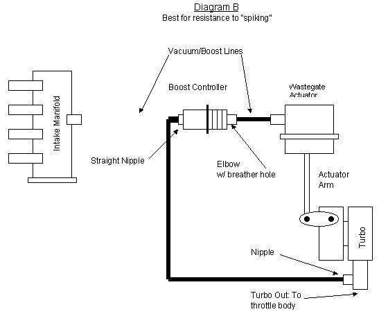
It's not weird, this has been for a long time you just didn't know . When taken directly from the manifold, a boost controler is not affected at all when it sees vac, however, the response to control boost and spiking would be noticeable more if taken from the manifold that taken directly from the turbo.

I've been using the good old "grainger valve" boost controllers since about 10 yrs now and never had a complaint about. This was Tomas Gus Mahon legacy to the turbo world.

I took these pics and explanation from the site of my good friend Dawes

This is a Hybrid Boost Controller, cheap and very very effective.


"Locate a boost source using the diagrams as a guideline. Now run a piece vacuum hose between the boost source and the straight end of the controller. A drop of oil on the brass tip will aid in adjusting the hose later. Do not use the original wastegate line as your boost source. The best place to use is a nipple on the turbocharger output, if you have one. If there is already a line attached, install a vacuum tee (as close to the nipple as possible). Alternate sources include the intake manifold, or the pipe between the turbo and throttle. Do not tie wrap this hose yet. You will need to rotate the hose about the nipples later. "

Diagram A


Diagram B
+ Reply To Thread
  • [Type to search users.]
  • Quick Reply
    Thread Information
    There are currently ? users browsing this thread. (? members & ? guests)
    StubUserName

    Back to top