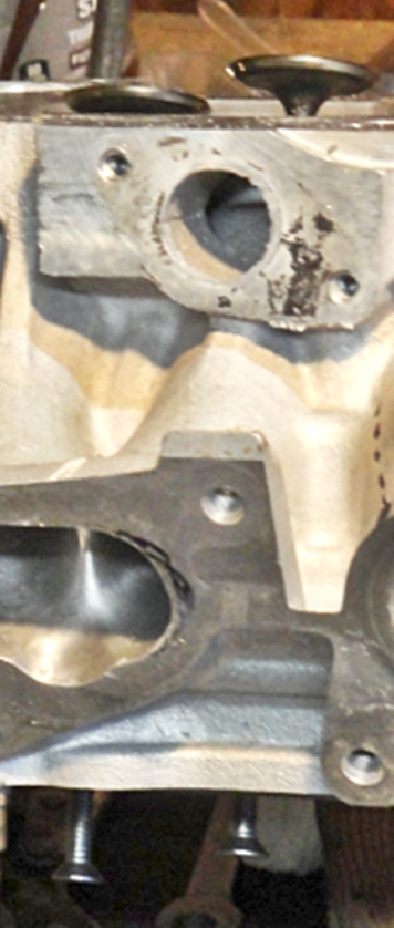
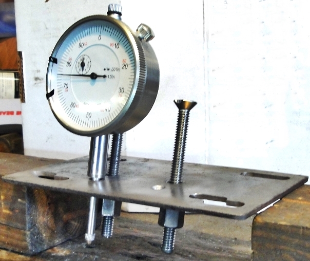
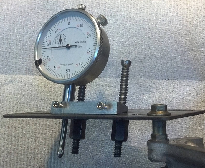
Now... where was I before I got us side tracked on tool development....

Oh yes...

Originally Posted by
oldeskewltoy
1 - as I mentioned, the casting is a bit rough leaving many areas containing sharp edges. From my experience, often times poor casting areas lead to sludge build up because the oil and debris sits in these areas "cooking" into place as the miles go by. Making these areas less prone to holding the oil and debris, helps keep the engine cleaner, and easier to shed oil back into the oil pan. A second, and purely selfish purpose is with me constantly changing its position on my porting bench, the roughness really hurts my hands..... 
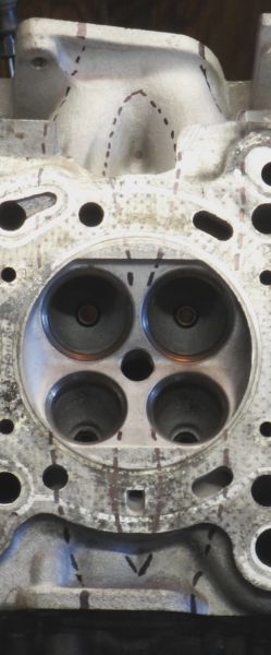
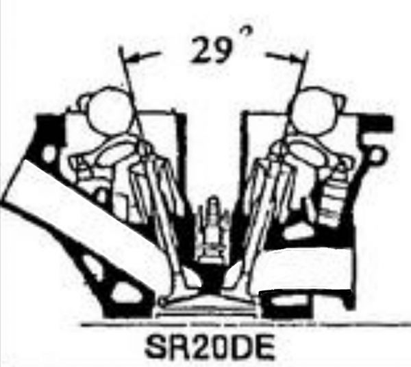
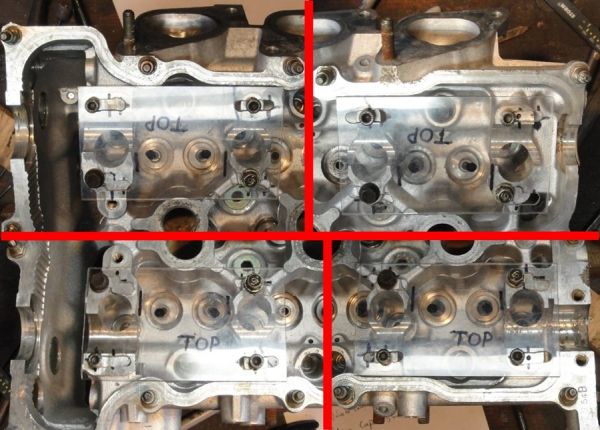
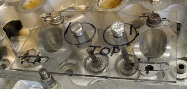
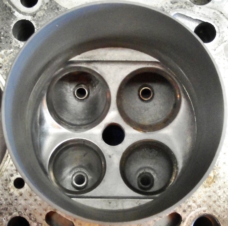
2 - below is a view of the Chambers #3 and #4 , I've blacked out the valve openings to avoid distraction.... 
As you can note, other then doing a tiny bit of blending around the seats, putting a ~.020" radius on both "squish" pads, and polishing the chambers I've had to do very little.
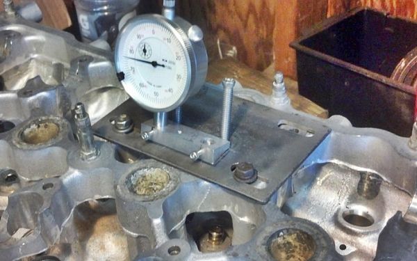
A small addition , as for the roughness/sharp edges, you can see preliminary deburring in the photo above that shows the tool mounted to the head. You can see where I ran the carbide cutter along some of the edges.
As far as chamber shapes - and, in fact, all the work I'm performing is "on a budget". So.... I will not be welding and re-shaping combustion chambers, that is prohibitively expensive (Thousands$$$) because for the most part less than .5% of you would ever consider paying for that kind of modification. Typically I delivery a finished product for well under $1000.
So we have discussed the casting and its requirements, and the combustion chambers. Now we come on the difficult part trying to increase the cylinders breathing capability. Note I said increase, because I'm NOT looking to discard(swap) low speed performance, in favor of high speed performance. The best goal is to provide a
W I D E powerband.
Borrowing Martins dyno, I've made a few alterations
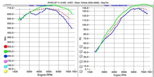
The dotted red lines I see as air flow problems(or how they will respond once corrected), the green lines is the desire for MartinS engine once we put this heads development into practice, along with his camshaft choice and appropriate compression bump.
A few different views of the intake port passages....
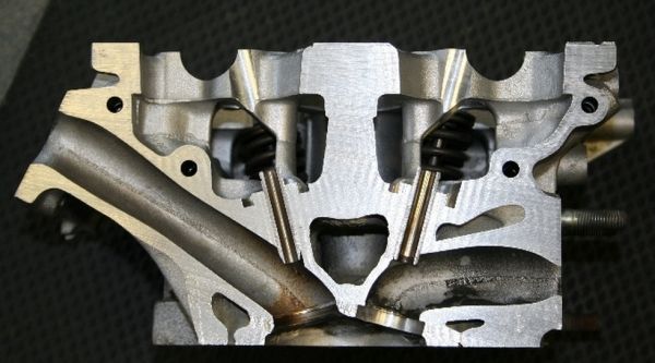
Now compare those views with a few others.....

Same similarities... while there are other differences....
Two of the views above seems to show the SR20 intake ports to have a similar shape to a Formula One design

but hold on... the F1 design doesn't have an HLA to avoid :angry:, the top view showing the port layout is our issue here. The port opening is marginally 50mm (do to costs, the port opening varies at the seam from 49 to 50),
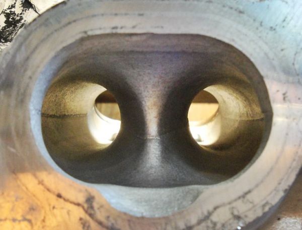
the intake valves are less than 9mm apart from each other,
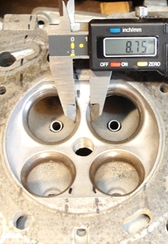
and the HLA makes the port splitter somewhere close to 23-24mm at its widest point.... and so you get a bow legged intake port.....
More can be done here ... mostly because this is a production automobile head, and as such typically there is enough casting material available to better shape, not only the intake port... but often the entire head.
More to come.......


 Be the first to like this post.

 Be the first to like this post.
 Be the first to like this post.
 Be the first to like this post.

 Be the first to like this post.
 Be the first to like this post.

 Be the first to like this post.
 Be the first to like this post.


 but hold on... the F1 design doesn't have an HLA to avoid :angry:, the top view showing the port layout is our issue here. The port opening is marginally 50mm (do to costs, the port opening varies at the seam from 49 to 50),

