Welcome to the SR20 Community Forum - The Dash.
Register
SR20 forum logo

Thread: The end of the road for VVL?

+ Reply To Thread
Posts: 21-25 of 25
2011-02-12 01:43:12
#21
there is no reason why this can work in a vvl engine. The amount of stuffing around to get a system like this working means that lifters are the last of your issues. Plus the spit in the middle of the camshaft makes me think you will be going through follows quite often anyway.

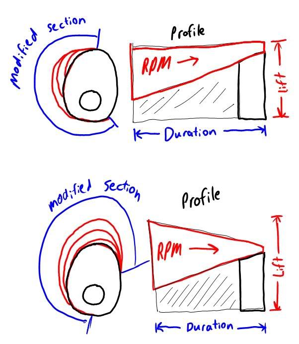
In regards to lift......as long as the cam is still ramping up where the added duration is, there is no reason you can get more lift with it as the duration adds. Its just depends on there the split location on the lobe is.

I dont like how you cant really change the ramp of the cam
Last edited by ca18 bluebird on 2011-02-12 at 01-53-28.
2011-03-01 10:55:44
#22
I have just noticed this thread. I have to confess to start with that although I am not the inventor of the Helical Camshaft system I wrote all the material on Wiki, the HC website and I have witnessed most of the design, construction and testing of the various cams - so I am very familiar with the whole HC business. Due to an almost total lack of interest from car companies etc. the inventor has gone off in a bit of a huff and is working on new projects - the HC being somewhat left on the backburner.
Consequently I have appointed myself to try and promote the HC at every opportunity.

Some points on some of the matters raised in the thread so far:

I (we) have not felt the need to over-exaggerate or bullshit generally about the HC. It basically does everything claimed (and demonstrated) of it - it really is the only existing all-mechanical wide range continuously variable at-full-lift duration system. You can debate endlessly that Valvetronic (or whatever) can do the same as the HC - but they can't - the HC is truly one-of-a-kind.

Mr. Fenner seems to like the Ferrari system. This 3D lobe is a perennial favourite of variable cam timing inventors and the idea has been around for many years. There is a basic and fatal flaw in the 3D lobe idea - the base circle region is parallel to the axis of cam rotation but the flanks and lobe nose are distinctly non-parallel. This requires then a tilting or ball-ended (both have been suggested in patents) follower - neither can be arraged satisfactorily. It seems to be something of an urban myth that Ferrari used this system in production cars - they never did - and (as far as I know) never used it in racing engines either. More on the Wiki discussion page on this subject.

One slight mistake in what seems to be a very well informed forum - the HC displayed a 40% improvement in idle fuel consumption when LIVC-controlled compared to the same idle RPM when throttle-controlled. Not a 40% increase in power.

On the subject of centrifugal controllers - this engine is a Daihatsu Charade shown running on the website video. To confuse matters slightly the engine does not have the HC pattern cam but an earlier, related type that only has (and is limited to) about a range of about 40 crankshaft degrees. There is another similar cam to this fitted to a Ford EA straight six. This has been used extensively on the road and dyno-tested. It recorded about a 30% improvement in power at about the same RPM of the original power peak (about 4200RPM) with an increase in duration of 32 degrees (which is all it has due to a slight miscalculation).

On the subject of fragility (or otherwise) of the variable cams: neither the HC or the earlier type of cam (we usually call them Type 1 and Type 2) have ever shown any wear or breakage problems - the EA cam was run to over 5200RPM on the dyno - I didn't realize that EAs were capable of such RPM - but it didn't worry the cam. Whether they would last twenty years is another matter - but they probably could be developed to do this.

The prototype HC cam that was run in a Suzuki 250GSX was without any automatic varying mechanism at all - the engine had to be stopped and manually adjusted. A centrifugal controller is a possibility for the HC but hydraulic actuation would seem more logical. In the Suzuki 25mm of movement along the cam axis gave a duration chage of 85 degrees - because of the geometry of the system this would be typical of all engines with an HC. Note that the duration increase is only limited by the room for axial movement. If you have axial room the two lobe flanks can meet - 720 degrees of duration.


Anyhow pretty much every thought we have had on the subject of the HC is in the Wiki article and website - so anything I write here is just repeating this material.

On the important question - the application of these cams to SR-style vakve gear. We only became aware about a year ago of the similarity of the SR valve gear to the Suzuki GSX when it was pointed out to us. We have never actually seen SR valve gear in the flesh (so to speak). From all the available images on the internet it would seem likely that a variable cam could be adapted to the SR engine. Common sense would suggest that the earlier (Type 1) with centrifugal controllers would be easiest to adapt - but the full-on all-singing/all-dancing HC is certainly a possibilty.

If there is enough interest I am sure we could be persuaded to build (or attempt to build) a prototype for an SR engine. But the Helical Camshaft Company would most likely not manufacture or market the cams - someone who understands business things can do that.

As for the application of the HC etc. to other makes of twin-cam engines - I think it would probably generally need a new head built to the general layout of the SR head - which would not be a bad thing - they seem to have nicely-shaped ports etc.

Do you think that there would be much of a market for variable-cammed heads - for SRs or other engines?

If you have any questions etc. I (we) are happy to attempt answers either through this forum or through the address given on the HC website.

If you live in the Newcastle (in Oz) area and are interested in seeing the HC run (and do its fuel-saving trick) - it can be arranged (with a few days' warning).
2011-03-09 03:31:33
#23
I am not sure that I am understanding exactly how this works, but... could the constant variable duration of the HC cam technology not be applied to both the high and low lobes of an SR20VE style cam allowing for continuously variable duration AND the standard variable lift? It seems, from my rather un-informed standpoint, that the far superiority of flow in the VE head would make much better use of this technology than a DE head.
2011-03-09 14:28:26
#24
I don't see that happening Will. There isn't enough lateral room for this design to retain all three VE lobes I don't think. It would make much more sense to replace the two straddling "low" lobes and the central "high" lobe with one variable duration lobe. However it couldn't be put in the center, as that follower needs high oil pressure to work. You'd end up having to put two of them per cylinder to act as "low" lobes and just forget about the center lobe all together. Make them high lift and "aggressive" but control low rpm power production and idle quality with very short durations.

It would be MUCH easier to do on the DE head.
2011-03-14 17:47:59
#25
Probably cannot be retrofitted into a VE, unless the moving section were much smaller and more aggressive (1mm of lateral movement = 5mm of lateral movement on the current prototype).

Secondly, While race applications would work on a simple centrifugal spring setup, actual production would most likely be computer controlled, both for reliability and fuel economy. The cam profile wouldn't be dependent on just RPM, but also throttle position and other possible parameters. Note the Greddy MSS, which allows multiple parameters for VVL activation. Although most only use one parameter (RPM) other factors can be programmed into the input.

Lastly, While this helical cam profile allows only modification of the duration, I see no reason it can't also modify lift. In his example, the fixed portion of the cam is the ramp-up section which includes the highest point of the lift, the modified portion stays with the highest point and includes the ramp-down section. Here's a bad sketch of what it could look like for a modified ramp-up AND ramp-down:


There are some extra downsides, for example, it would cost more to machine a cam at those angles, not to mention, the profile would have to be hydraulically controlled for the added pressure of moving the cam.
+ Reply To Thread
  • [Type to search users.]
  • Quick Reply
    Thread Information
    There are currently ? users browsing this thread. (? members & ? guests)
    StubUserName

    Back to top