I TAKE NO RESPONSIBILITY FOR ANY MISTAKES, OR FAILURES IN ATTEMPTING THIS. YOU DO SO AT YOUR OWN RISK. Take your time and do it right the first time to avoid any problems.
At the time of this write up, I do not have a VE in my B13, nor is B13 readily available for me to verify wire colors. My B13 is a 93, and the wire colors I will be using in this write up are for the 94.
There has been a desire, for a write up on how to wire the VE distributor into your B13 harness since 2002. I have yet to see anything for this, so I took the time to do some research and came up with a way to eliminate all of the old, outdated DE distributor stuff, and replace it with the newer, more efficient VE distributor.
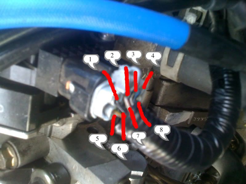
Use the picture of the VE dizzy plug as reference.

1 - Ground
2 - Power - ECCS Relay
3 - Cam position sensor #3
4 - Cam position sensor #4
5 - Distributor resistor/ IGN Check
6 - IGN Switch
7 - Ground
8 - Distributor Power/ IGN Signal
When you wire in to the B13 you will be eliminating;
Coil
Resistor and condenser
Power transistor
Crank angle sensor (inside DE distributor)
The view of the plugs is from the terminal side and not the wire side of the plug. The numbers I state below are for the female plug, aside from the VE, which are all part of your engine harness. The VE plug for the distributor is male, and I have those pins numbered from the wire side. Use the picture above for reference.
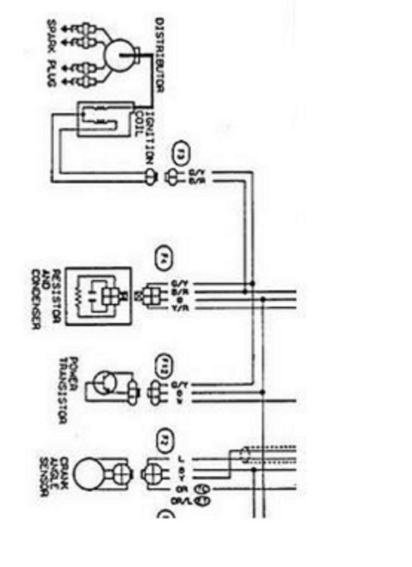
Use this pic from the B13 FSM for reference.

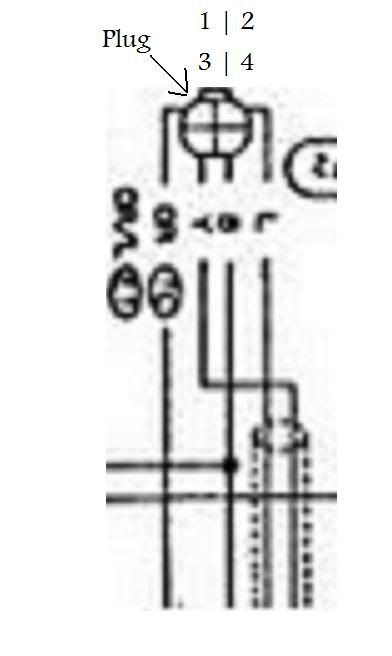
For the crank angle sensor in the distributor (the 4-wire plug that goes to the dizzy) the wires will go to;
DE - VE
1 - 2
2 - 4
3 - 3
4 - 1
Use this pic for the DE crank angle sensor plug.

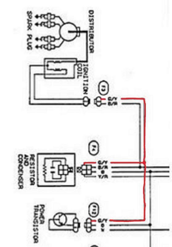
For the coil, resistor/condenser, and power transistor, you will be eliminating these three and combining wires/ eliminating wires to simplify and wire to the remaining 4 wires of the VE plug.
They will be as follows;
Eliminate the G/Y wire highlighted in red
DE - VE
B/R - 6
B - 7
Y/R - 5
W - 8
Use this pic.

From what I’ve read, there are 2 plugs for the VE, both configured the same, but a few of the wire colors vary. The wire colors that I am using in this write up are for the 1994 Nissan Sentra SE-R, but the plug arrangements are the same for the B13’s. If while trying to do this in your B13 you notice an inconsistency in a wire color, refer to the pics above to verify it’s position in the plug and where it needs to go.
Use this link for the B14. It was written back in 2002, but is what I used for my B14 and it works perfect. I do not take credit for the information in this thread, but I will 100% vouch for the information as being accurate and correct.
DE to VE distributor wiring - SR20 Forum
Using the information I have provided you in this thread and in the link to the other thread, you will now be able to wire up your VE’s distributor to work in your car instead of having to cut up an old DE distributor to fit the VE head.
At the time of this write up, I do not have a VE in my B13, nor is B13 readily available for me to verify wire colors. My B13 is a 93, and the wire colors I will be using in this write up are for the 94.
There has been a desire, for a write up on how to wire the VE distributor into your B13 harness since 2002. I have yet to see anything for this, so I took the time to do some research and came up with a way to eliminate all of the old, outdated DE distributor stuff, and replace it with the newer, more efficient VE distributor.
Use the picture of the VE dizzy plug as reference.

1 - Ground
2 - Power - ECCS Relay
3 - Cam position sensor #3
4 - Cam position sensor #4
5 - Distributor resistor/ IGN Check
6 - IGN Switch
7 - Ground
8 - Distributor Power/ IGN Signal
When you wire in to the B13 you will be eliminating;
Coil
Resistor and condenser
Power transistor
Crank angle sensor (inside DE distributor)
The view of the plugs is from the terminal side and not the wire side of the plug. The numbers I state below are for the female plug, aside from the VE, which are all part of your engine harness. The VE plug for the distributor is male, and I have those pins numbered from the wire side. Use the picture above for reference.
Use this pic from the B13 FSM for reference.

For the crank angle sensor in the distributor (the 4-wire plug that goes to the dizzy) the wires will go to;
DE - VE
1 - 2
2 - 4
3 - 3
4 - 1
Use this pic for the DE crank angle sensor plug.

For the coil, resistor/condenser, and power transistor, you will be eliminating these three and combining wires/ eliminating wires to simplify and wire to the remaining 4 wires of the VE plug.
They will be as follows;
Eliminate the G/Y wire highlighted in red
DE - VE
B/R - 6
B - 7
Y/R - 5
W - 8
Use this pic.

From what I’ve read, there are 2 plugs for the VE, both configured the same, but a few of the wire colors vary. The wire colors that I am using in this write up are for the 1994 Nissan Sentra SE-R, but the plug arrangements are the same for the B13’s. If while trying to do this in your B13 you notice an inconsistency in a wire color, refer to the pics above to verify it’s position in the plug and where it needs to go.
Use this link for the B14. It was written back in 2002, but is what I used for my B14 and it works perfect. I do not take credit for the information in this thread, but I will 100% vouch for the information as being accurate and correct.
DE to VE distributor wiring - SR20 Forum
Using the information I have provided you in this thread and in the link to the other thread, you will now be able to wire up your VE’s distributor to work in your car instead of having to cut up an old DE distributor to fit the VE head.


 Be the first to like this post.
 tested and working in my B13 but the tach don`t work but conect the wire of tach to wire 5 on the VE dist. connector

 Back to top
