Welcome to the SR20 Community Forum - The Dash.
Register
SR20 forum logo

Thread: Prepping for MAP conversion

+ Reply To Thread
Posts: 21-30 of 101
2013-05-07 11:22:44
#21
Originally Posted by lynchfourtwenty
i should have plenty of outputs left.. only used the o2 sensor one so far lol


If you do use the ECU to control the fan MAKE SURE YOU USE A RELAY!

The ECU outputs are not made to drive something like the fan directly and must use a relay in line.
2013-05-07 13:19:58
#22
Originally Posted by lynchfourtwenty
i should have plenty of outputs left.. only used the o2 sensor one so far lol


O2 sensor is an input, so you haven't actually used an output.

Cheers,
Dave
2013-05-07 13:40:35
#23
Man this looks so confusing man i'm getting a bit nervous now
2013-05-07 14:43:42
#24
Originally Posted by OnTheChip
Originally Posted by lynchfourtwenty
i should have plenty of outputs left.. only used the o2 sensor one so far lol


O2 sensor is an input, so you haven't actually used an output.

Cheers,
Dave


oh, i thought using the o2 heater to activate vvl counted has output? my bad.

Originally Posted by JKTUNING
Originally Posted by lynchfourtwenty
i should have plenty of outputs left.. only used the o2 sensor one so far lol


If you do use the ECU to control the fan MAKE SURE YOU USE A RELAY!

The ECU outputs are not made to drive something like the fan directly and must use a relay in line.


totally! i was thinkin last night how i'd go about that.. maybe i could just hook one of the outputs to that white wire w/ green stripe that goes to the relay.. now that i know what it does.. i plan on going ape shit with the multimeter today lol

Originally Posted by Scrildo
Man this looks so confusing man i'm getting a bit nervous now


well im doing my best to document this so that other guys have an easier time haha.
2013-05-07 14:57:29
#25
Originally Posted by lynchfourtwenty

oh, i thought using the o2 heater to activate vvl counted has output? my bad.


O2 sensor is an input, O2 heater is an output.

Cheers,
Dave
2013-05-07 16:43:20
#26
Originally Posted by Scrildo
Man this looks so confusing man i'm getting a bit nervous now


If you have any specific questions you can always ask on here or just shoot me an email.

I would suggest keeping it simple and just running your own wiring instead of hacking into the stock harness, especially if you are unsure of some of the wiring.
2013-05-07 17:31:16
#27
Originally Posted by Evlnxr
With one resistor like the original diagram my sensor was way out of calibration, was 105deg C with engine not running, and there would not have been any resolution left if i calibrated it like that. Putting another resistor in brings the voltage up a bit higher to the signal.


I specified a 5k ohm to limit the current draw when thermistor resistance is low. Wiring two 5k ohm resistors in parallel is the equivalent of 2.5k ohms, doubling the current draw. While I have not tested the upper current limit of the 5V supply in the breakout box, I suggest using at least 5k ohms and calibrate by shifting the IAT conversion table. There should be plenty of resolution in a reasonably expected IAT range.

If I had the ability, I'd attach an excel sheet that shows the voltage based on divider resistor. (Vadim?)

Cheers,
Dave
2013-05-07 19:37:22
#28
OK so IGNORE the white wire with green stripe!!!

that little suckers all over the place.. it not only goes to the AIV and EGR canister plugs but it leads to the white dash plug, from there it goes to (i think) the fan relay under the hood and then the fuse box in cabin to the engine control fuse, or something along them lines.. So using it for a ground was highly foolish, i should have checked into it more.. BUT NOW YALL KNOW..

i replaced the burnt fuse and now my rad fan works again, so no need to macgyver that shit... This time...

im going to keep it simple and run external grounds, i already utilized the pink and grey wires from the AIV and EGR canister stuff which is all good..
2013-05-08 19:44:07
#29
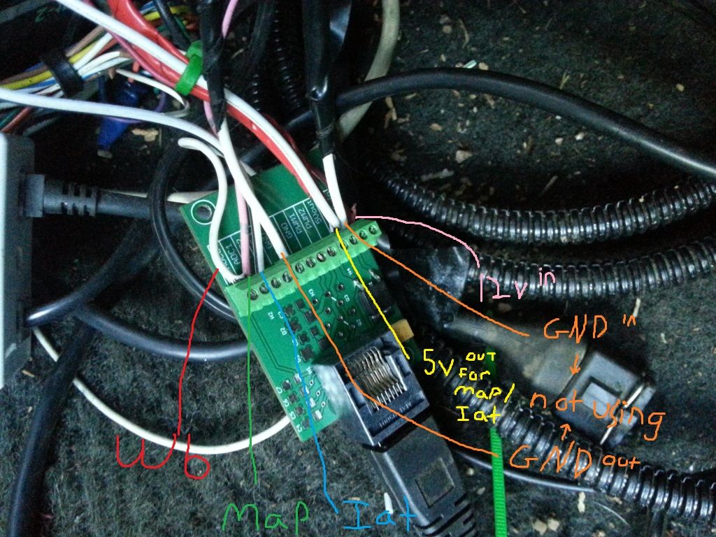
alright i finally got the map an iat wired up! yay! ended up just running a ground from the map an iat to where my ecu an maf are grounded.. made life simple! lol

you can see here, at first i tried utilizing the pin 21 ecu ground, wasn't working tho.. so went the other route.. however everything else remained but i dropped the grounds..


i know my wire selection is limited but thats ok, i know whats what

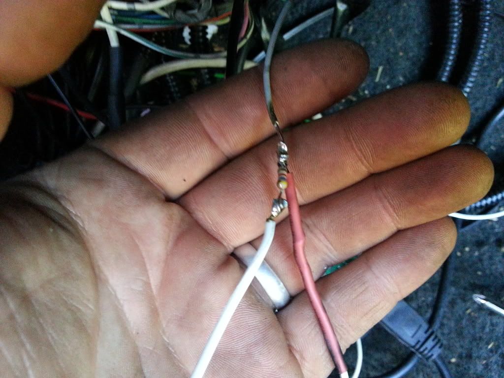
in this pic you can see how i wired up the resistor, what i did was ran a wire from the 5v out to one side of the resistor, then i peeled part of the insulation back on the grey wire im using as signal from the iat sensor and attached the resistor there, then the end of the grey wire goes to adc


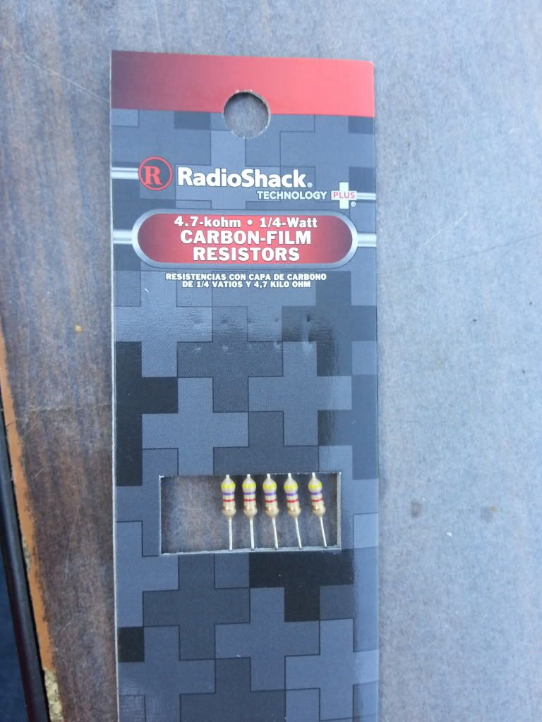
this is all i could find at my local radioshack


hopefully that resistor will work ok..

i tried to solder everything an use heat shrink.. having an inverter in the car kicked ass for using the soldering gun hehe
2013-06-10 17:29:23
#30
@lynchfourtwenty, how did this setup work for you? Everything working okay?
+ Reply To Thread
  • [Type to search users.]
  • Quick Reply
    Thread Information
    There are currently ? users browsing this thread. (? members & ? guests)
    StubUserName

    Back to top